Studying the ml1 schematic i see that it has a rather unsual feedback arrangement mainly the 2uf cap from the negative input (or c9 in the 2nd schematic)
What is the role of this cap and how does it affect the frequency response?
The reason why i ask is that i recently had a chance to compare my homebrew pre to a mark levinson ML1 and the latter had 'more' bass, according to its owner
What is the role of this cap and how does it affect the frequency response?
The reason why i ask is that i recently had a chance to compare my homebrew pre to a mark levinson ML1 and the latter had 'more' bass, according to its owner
Attachments
Seems to be just ordinary dc decoupling of the nfb, i.e. 100% nfb at dc. 99% of standard amps have a similar cap. It has to be large enough compared to the resistor to ground in order to not affect low frequency response. It's quality is critical to the perceived sound.
Right but its the arrangement that looks unusual to me. Usually the cap is between the ground and the shunting resistor, not between the opamp and the resistor.
Maybe the way its arranged on mark levinson it creates a high pass filter for the opamp?
Maybe the way its arranged on mark levinson it creates a high pass filter for the opamp?
In thge normal situation, the C and the R in the feedback to ground leg are in series so can be interchanged. Cap on top, R on bottom doesn't change anything.
What they appear to do here is adding an extra resistor to limit the feedback at DC to less than 100%. So this amp has some DC gain (R12/R13). Why they did that, I don't know.
Jan
What they appear to do here is adding an extra resistor to limit the feedback at DC to less than 100%. So this amp has some DC gain (R12/R13). Why they did that, I don't know.
Jan
Jan are you talking about the 47k? Because r12/13 are just regular feedback resistors.
Ill butcher up one of my opamp modules to see what effect this arrangement has.
Once again the old ml1 sounds very 'bassy' compared to a flat FR modern preamp. Seeing as how ml1 is dc coupled i think the 'bassyness' might has to do with the feedback
Ill butcher up one of my opamp modules to see what effect this arrangement has.
Once again the old ml1 sounds very 'bassy' compared to a flat FR modern preamp. Seeing as how ml1 is dc coupled i think the 'bassyness' might has to do with the feedback
I found my answer here
https://www.tubecad.com/2015/05/blog0323.htm
But still wouldnt this additional 100k resistor counter the benefit of lowered noise?
Ill definitely p2p this and report back
https://www.tubecad.com/2015/05/blog0323.htm
But still wouldnt this additional 100k resistor counter the benefit of lowered noise?
Ill definitely p2p this and report back
Attachments
"Ill butcher up one of my opamp modules" - don't do that (they are expensive on the used market) and the feedback arrangement is outside the modules anyway. Besides that they are filled with epoxy inside, so most likely you will just destroy them.
"p2p" - keep in mind that the semiconductors used (those are designed 1974) are long gone and unavailable.
The feedback at DC is 100% and the DC gain thus 1.
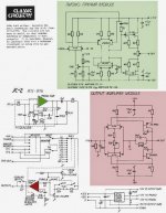
The second picture has a drawing error for the line module, the first one is correct.
I have attached a simulation file for LTSpice with JFets from Linear Systems.
"p2p" - keep in mind that the semiconductors used (those are designed 1974) are long gone and unavailable.
The feedback at DC is 100% and the DC gain thus 1.
The second picture has a drawing error for the line module, the first one is correct.
I have attached a simulation file for LTSpice with JFets from Linear Systems.
Attachments
Oh no! Im saying ill try this feedback arrangement on my homebuilt preamp.
Mark levisons' recent models still use this method. Im guessing the caps are mkt wima
Mark levisons' recent models still use this method. Im guessing the caps are mkt wima
Having had a look at what Tubecad said about this circuit, I thought a simulation in LTspice would be a good idea.
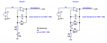
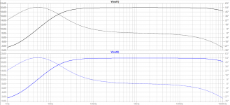
In circuits.asc, Circuit 1 has a voltage gain of 20dB and employs a DC blocking capacitor C2 in the familiar, "traditional", configuration, in series with R2. Circuit 2 also has a gain of 20dB but the DC blocking capacitor C4 is now in the "Levinson" configuration under discussion. (See Circuit.PNG)
Both circuits have the same frequency response, with a low frequency turnover of around 15 Hz (see FrequencyResponses.PNG). However, there is a striking difference in the two circuits, namely that for the same low frequency response, C4 only needs to be 1/100 of the size of C2. C4 can be either a much cheaper component, or a higher quality one, for the same outlay.
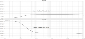
This sounds like a free lunch at first, but the fly in the soup is the low frequency noise characteristics of the two circuits. For the traditional circuit, the low frequency noise at the output falls off in tandem with the frequency response. For the Levinson arrangement, the low frequency noise increases significantly. In the pass band, the noise is essentially the same for both circuits. (See Noise.PNG)
The Levinson circuit therefore gives us a way to trade off the size/quality/cost of the DC blocking capacitor with the noise at low frequencies, a useful addition to the designer's armoury. The noise can be pushed to a low frequency where, hopefully, it can be made inaudible and will not interfere with the audio.
In circuits.asc, Circuit 1 has a voltage gain of 20dB and employs a DC blocking capacitor C2 in the familiar, "traditional", configuration, in series with R2. Circuit 2 also has a gain of 20dB but the DC blocking capacitor C4 is now in the "Levinson" configuration under discussion. (See Circuit.PNG)
Both circuits have the same frequency response, with a low frequency turnover of around 15 Hz (see FrequencyResponses.PNG). However, there is a striking difference in the two circuits, namely that for the same low frequency response, C4 only needs to be 1/100 of the size of C2. C4 can be either a much cheaper component, or a higher quality one, for the same outlay.
This sounds like a free lunch at first, but the fly in the soup is the low frequency noise characteristics of the two circuits. For the traditional circuit, the low frequency noise at the output falls off in tandem with the frequency response. For the Levinson arrangement, the low frequency noise increases significantly. In the pass band, the noise is essentially the same for both circuits. (See Noise.PNG)
The Levinson circuit therefore gives us a way to trade off the size/quality/cost of the DC blocking capacitor with the noise at low frequencies, a useful addition to the designer's armoury. The noise can be pushed to a low frequency where, hopefully, it can be made inaudible and will not interfere with the audio.
Attachments
It would be interesting to simulate a non-linear capacitor when comparing the two topologies to campare the sensitivity to that non-linearity as a function of frequency and of amplitude.
- Home
- Source & Line
- Analog Line Level
- Mark levinsin ml1 feedback schema