Hey all.
I've had another thread running on another forum but I need confirmation on my crossover circuit layout before I can glue it down, and everyone is being a bit quiet over there... I've never really done much/anything with electronics before, or speakers for that matter... or woodworking... so I need re-assurance in some areas.
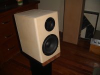
So far I've completed one speaker box, and I've begun to assemble the crossovers. Very near to having one completed speaker (once I buy the drivers and other small parts).
Here's the diagram for the crossovers, and what I've interpreted it as in my layouts.


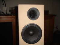
Also, here's how the speaker box is looking right now -

I've had another thread running on another forum but I need confirmation on my crossover circuit layout before I can glue it down, and everyone is being a bit quiet over there... I've never really done much/anything with electronics before, or speakers for that matter... or woodworking... so I need re-assurance in some areas.
So far I've completed one speaker box, and I've begun to assemble the crossovers. Very near to having one completed speaker (once I buy the drivers and other small parts).
Here's the diagram for the crossovers, and what I've interpreted it as in my layouts.
Also, here's how the speaker box is looking right now -
looks fine to me, (actually far too neat... 😉), I'd cut off the unnecessary extra pieces of wire from the solder joints to avoid any possibility of shorts
Hi
I am building er18 as well
Managed to connect one crossover briefly just to check how it works..
And no sound from tweeter
Can I check with you my connection ?
I have 3 inputs on terminals bar.. 1 2 and 3
from input #1 I have R1 to C2 which return to terminal #2
from #2 I have c4 to L3 to to r3 which return to #3
from ~2 I have c5 to L4 to r4 which returns to #3 ?
And the wire from #3 goes to woofer's input #3
Amplifier to crossover wires go to #1 and #3 each
crossover to drivers go from #2 and #3 ?
Don't know ho to explain in different way.. pardon 🙂
Ooops...
it seems I need to connect all grounds together: r3 r4 and tweeter positive to the ground.
it seems I need to connect all grounds together: r3 r4 and tweeter positive to the ground.
Sounds like you've already sorted it out.
But here's how mine is done and it seems to work on my test speakers.
The unmarked points are the positive speaker wires.

But here's how mine is done and it seems to work on my test speakers.
The unmarked points are the positive speaker wires.
I made a circle jig to do the routing, so it was really easy.
I bought a jigsaw and some 3mm MDF. Traced the bottom of the router on to the MDF, and added on a bit of length for wide circles. That's the one on the right. Turns out I shouldn't have cut out the inside, as I needed it to cut smaller diameter circles... so I made another one for smaller diameter circles (the tweeter cutouts).
If you don't have a circle jig, I recommend making one like I did. Except don't cut out the inside... just do a plunge with your widest router bit when it's screwed on to the base. So essentially turning my two jigs in to one 🙂
Narrow enough to fit inside the speaker cabinet, and tall enough to fit all the components. I think they were 110x180 or so. Not sure, didn't do much measuring for them.
Tandata, just want to double check
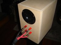
Which port did you choose ?
Mark says the one from parts express.
But here in europe it is not available- so I need to look for alternative.
It has to flared ..
2 inch diameter
and 11 inch length (which I think too long, but I could be missing something)...
Which port did you choose ?
Mark says the one from parts express.
But here in europe it is not available- so I need to look for alternative.
It has to flared ..
2 inch diameter
and 11 inch length (which I think too long, but I could be missing something)...
I don't bother with terminal strips. I just leave extra length in case I need to snip to rework, and when testing is finished I re-solder with minimum lengths. I hate those Euro-style strips.
- Status
- Not open for further replies.
- Home
- Loudspeakers
- Multi-Way
- Mark Ks ER18DXT