Well I thought I'd show some progress on one of my amps in Progres. In about 2019 I had contacted Phil Marchand for a PM224 kit. Phil told me he really didn't sell diy amp modules kits any more but I implored him, and he relented, putting together a
PM224 R1218
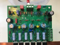
kit for me. I told him to take his time in putting the kit together and it was Christmas so I wasn't in a big hurry. Some time later I received my kit. To be honest I had never seen this version of the PM224. It seemed to me the VAS stage was different and there was no facility to separate the power feeds between the output and front stage. I went about building the amp module and tested it and all was awesome! I put it on a shelf and went about collecting and making the different parts for the amp.
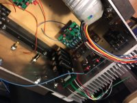
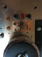
There is a diyaudio Soft Start and Speaker Protection kit, as well I created a custom, multi-capacitor bank (akin to the old adage that many are always superior to the equivalent of the one). I always wanted to try a CRC based filter and I'd been exposed to a lot of different PS configurations in my job as a cnc/electronic technologist and decided to try a combination of CRLC. I've used CLC filters and I thought maybe there was a best of both worlds here.
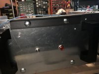
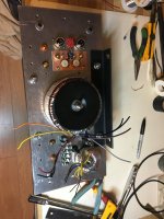
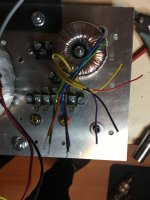
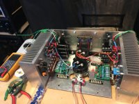
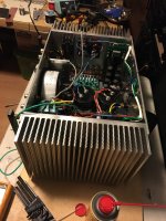
well most my parts collection was completed about 2 years ago but I fell ill and all went on a back bench. I've been poking away at it lately and my god I'm actually getting somewhere. I got at least 60 taps completed in each of the heatsinks and parts positioning has been worked out other then one small transformer. It's taken quite some time and I've had help manipulating the larger/heavier parts. the transformer is a 25-0-25 500va Antek and I incorporated some parts from a CA-150.
I created custom 2mm copper heatspreader/anglebracket for them and I've had a bunch of these massive heatsinks I bought off a dude on the east coast many years ago (that was a MASSIVE shipping bill). I think each weighs about 20 lbs!!! and the trans weighs a ton also. I'm gonna have a friend put this on a small wheeled stand for me so I can move it around easier.
enjoy the photos and I should have this complete soon, it will remain my focus till this happens (I have too many projects going here, I gotta finish some!)
PM224 R1218
kit for me. I told him to take his time in putting the kit together and it was Christmas so I wasn't in a big hurry. Some time later I received my kit. To be honest I had never seen this version of the PM224. It seemed to me the VAS stage was different and there was no facility to separate the power feeds between the output and front stage. I went about building the amp module and tested it and all was awesome! I put it on a shelf and went about collecting and making the different parts for the amp.
There is a diyaudio Soft Start and Speaker Protection kit, as well I created a custom, multi-capacitor bank (akin to the old adage that many are always superior to the equivalent of the one). I always wanted to try a CRC based filter and I'd been exposed to a lot of different PS configurations in my job as a cnc/electronic technologist and decided to try a combination of CRLC. I've used CLC filters and I thought maybe there was a best of both worlds here.
well most my parts collection was completed about 2 years ago but I fell ill and all went on a back bench. I've been poking away at it lately and my god I'm actually getting somewhere. I got at least 60 taps completed in each of the heatsinks and parts positioning has been worked out other then one small transformer. It's taken quite some time and I've had help manipulating the larger/heavier parts. the transformer is a 25-0-25 500va Antek and I incorporated some parts from a CA-150.
I created custom 2mm copper heatspreader/anglebracket for them and I've had a bunch of these massive heatsinks I bought off a dude on the east coast many years ago (that was a MASSIVE shipping bill). I think each weighs about 20 lbs!!! and the trans weighs a ton also. I'm gonna have a friend put this on a small wheeled stand for me so I can move it around easier.
enjoy the photos and I should have this complete soon, it will remain my focus till this happens (I have too many projects going here, I gotta finish some!)
Attachments
-
 File_000.jpeg456.4 KB · Views: 158
 -
 IMG_2492.JPG434.7 KB · Views: 138
 -
 IMG_2491.JPG393.1 KB · Views: 137
 -
 IMG_2490.JPG447 KB · Views: 137
 -
 IMG_2489.JPG472.2 KB · Views: 126
 -
 IMG_2488.JPG410 KB · Views: 121
 -
 IMG_2487.JPG352.3 KB · Views: 126
 -
 IMG_2486.JPG489.5 KB · Views: 115
 -
 IMG_2486 - Copy.JPG489.5 KB · Views: 135

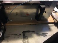
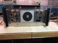
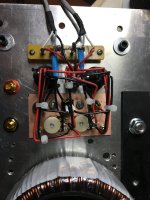
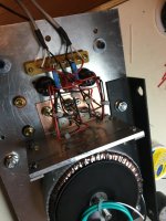
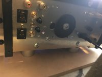
and this is some back panel work, balanced in level control with switching for single ended option to be wired. and I will be adding the switching to bypass the balanced in level control. that switch cost me a pretty penny, 4pole/double throw switches aren't cheap!
Attachments

Last edited:
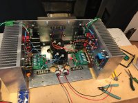
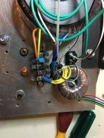
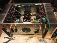
well, today I was able to find a spot for that small transformer. why is it always that you have to move this to accommodate that? just seems to happen every time. I also mounted the switch to short the balanced in pots. capacitors are mounted for the main part and the bottom is affixed to one side. always so much to consider. I think I've designed a pretty cool wiring layout for it. It should look neat, kinda got the idea from a tube amp I designed and built over 1996-1997 Edmonton awful winter weather, that was a seriously cold year there.
you know I thought I'd explain why I choose to go all out on a PM224. It was Marchands kits that really started me in the direction of building real high-end audio at home in the early 90's. I started with a W8 and then some active crossovers. I built a beautifully sounding amp out of a PM124 kit that was highly modified. 10 watts in class A and ran so hot you could fry eggs on it! I'd always wanted to build a PM224 kit with separate regulated supply for the front end. By the time I got to really committing Marchand didn't sell the kit anymore. So I begged Phil to put a special one together for me and I said take as much time as you need. I took about 2 months in total to get the kit. I built the amp module about 5 years ago and got it running really good but there was just so much I wanted to incorporate the execute on this bad boy. I just needed a serious kick in the *** to just put together all this darn work I did so long ago
anyways here's some more photos... enjoy
Attachments
What I like about Marchand Amplifiers: by Shawnra
1. Marchand amplifiers are nice and work good.
2.They can be operated in Class AB or as deep into class A as your design is capable of handling.
3. They are very stable and hold bias and offset positions in place for extremely long periods
4. Phil Marchand is a pretty cool guy and I think one of the true pioneers for DIY mosfet based kits.
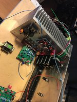
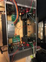
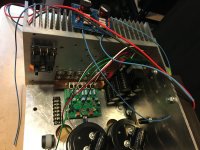
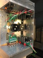
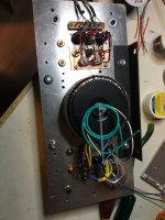
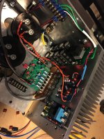
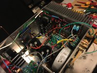
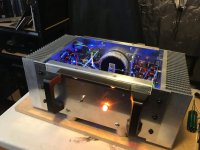
I got some more work done, that darn case is starting to get pretty crowded. Yeah I know some are thinking that back is never gonna fit back on. Well believe me it does, it is a seriously tight clearance but it does and that's what counts. Ran some nice ferrite beads on the secondary ac feed. routed +V and -V. Tomorrow, once the back is on, I'll route the star grounding configuration. Wait for it cause I think it's gonna look pretty cool 🙂
I also incorporated my RL filter board. There's a 0.05mH@10amp choke on the feed to the capacitors on the bottom and 4X0.47ohm parallel resistors for each rail.
Just an Idea I wanted to try out, I'll be curious to see how it affects ac output ripple and other aspects.
some photos, enjoy
1. Marchand amplifiers are nice and work good.
2.They can be operated in Class AB or as deep into class A as your design is capable of handling.
3. They are very stable and hold bias and offset positions in place for extremely long periods
4. Phil Marchand is a pretty cool guy and I think one of the true pioneers for DIY mosfet based kits.
I got some more work done, that darn case is starting to get pretty crowded. Yeah I know some are thinking that back is never gonna fit back on. Well believe me it does, it is a seriously tight clearance but it does and that's what counts. Ran some nice ferrite beads on the secondary ac feed. routed +V and -V. Tomorrow, once the back is on, I'll route the star grounding configuration. Wait for it cause I think it's gonna look pretty cool 🙂
I also incorporated my RL filter board. There's a 0.05mH@10amp choke on the feed to the capacitors on the bottom and 4X0.47ohm parallel resistors for each rail.
Just an Idea I wanted to try out, I'll be curious to see how it affects ac output ripple and other aspects.
some photos, enjoy
Attachments
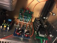
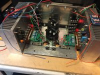
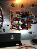
Okay, so I've gotten a bit further along. It has taken me several days but I wired the input. There is a switch for single ended or balanced and a switch to bypass input volume pot if needed. The single ended balanced mode works whether pot is in or out of the circuit.
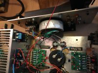
Put up a aluminum wall between main transformer and input wiring. I can now put the back on and start on the connecting up of the rest of the parts. Then onto grounding, which is a whole other topic.
some photos
Put up a aluminum wall between main transformer and input wiring. I can now put the back on and start on the connecting up of the rest of the parts. Then onto grounding, which is a whole other topic.
some photos
Attachments

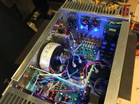
so I have another update, very close to powering up the power supply and I'll let it run for a day. just to reform any old caps and stuff. None of the caps are more then 7 years old so I imagine most are still good. the back is on I'll complete wiring this evening and power up. It's starting to look like an amplifier. It is quite heavy so I've required a lot of help but hey the end is near!
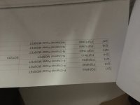
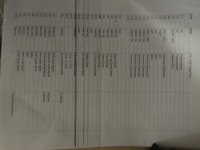
I included the parts list. I don't have a schematic, Phil wouldn't share it with me but I don't think it's too different then the last version. I've never had an amp based around FQP type output mosfets but I've heard really good reviews.
I included the parts list. I don't have a schematic, Phil wouldn't share it with me but I don't think it's too different then the last version. I've never had an amp based around FQP type output mosfets but I've heard really good reviews.
Attachments

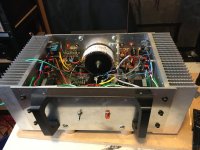
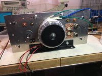
when you look at the amp from the side, you really start to get a feeling for the scale of this amp. It is one big, bad, boy!
I'm gonna guess it weighs 70 to 80 lbs. It was not my intention to make it so big. just a result of the parts I have on hand.
I'm gonna guess it weighs 70 to 80 lbs. It was not my intention to make it so big. just a result of the parts I have on hand.
Attachments

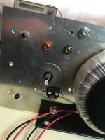
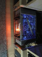
Okay, so I got the power rails up today and they are just gonna run without the amps connected for about 24 hours. Just to let everything settle in the power supply.
I gotta admit it is one mean looking amplifier. I think it has a bit of a menacing look to it?
The rails are closely matched and... who'd of thought it but that el cheapo toroidal is absolutely whisper quiet. I am impressed!
I also wanted to mention the the input circuitry is star grounded to itself, the input will join ground at the input terminals. I don't normally do that but I've been wondering lately about internal ground loops between wires and the case. I believe this to be a superior method. I'll let you know my findings.
Attachments


Last edited:
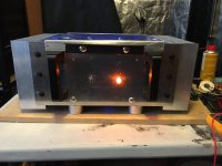
okay... WoW, success! dialed into 25 watts class A with the rest in AB. I've got 100 watts of some serious, *** kicking, wonderful sound.
MY goals for this project was a Class A amp that I'd be comfortable running in summer here in Winnipeg. It gets seriously hot here at times.
Of course my other goals were centered around sound quality and such as we all are on this forum. this amp just makes my speakers move way more then the amp I've been using. it almost like it's alive.
the sound is really quite amazing. I won't bore you with a lot of audiophile babble talk. suffice to say I'm extremely happy and this was 5 years well spent. I'm so grateful for the experience of having this amp in my head for so long until it came out in reality. I had to adjust my plans as I went along, as we all do when undertaking such an endeavor and in the end I can say I'm completely satisfied with how it looks and sounds. And that's a pretty hard response to get from me in the world of audio. some final photos
Attachments


- Home
- Amplifiers
- Solid State
- Marchand PM224 R1218