Hi,
Some folks kindly helped me adjust the Idle current on this amplifier but now I'm struggling with the DC offset and have started new thread in hope of some help.
I have taken a few measurements already but really I don't know what I'm doing! The DC offset is around 87mv once its settled down but as high as 100mv initially give or take a few mv.
The measurements in the attached give or take a few mv. I do know already the DC is supposed to be 60mv and I'm trying to reduce it as much possible to that figure. Any help appreciated. Thank you
Attachments
I believe 87mV offset is probably fine if you want to just live with it, but you can trim it to near 0V if you wish.
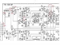
Assuming there are no other defects, the offset you're observing is almost certainly due to the mismatched bias resistors at the inputs of opamp Q701, namely R701 vs. R707--- 220K vs. 33K, respectively. This assumes there's no leakage through C701 and C713. (It's probably the charging time for these two caps that is responsible for the turn-on settling you've noted.)
So to reduce the output to 0, you need to force an additional 87mV drop across R707, i.e. 87mV/33K = ~2.6uA. To do that, install a resistor from the +17V rail to Q701 pin 3. The resistor value should be (17-0.103)/2.6uA = ~6.5M Ohm, say 6.8M Ohm.
😉
Last edited:
You must be some kind of genius! I will attempt matching the 220k and 33k first, I will be happy with just 60mv. Option B (0mv) looks more complicated.
I didn't mention I'm providing remote support and it has been recapped already mainly with Panasonic FM/FC.
I did notice that they maybe carbvon resistors at 5% tolerence, perhaps it has drifted? Update as soon as I can. Thank you
I didn't mention I'm providing remote support and it has been recapped already mainly with Panasonic FM/FC.
I did notice that they maybe carbvon resistors at 5% tolerence, perhaps it has drifted? Update as soon as I can. Thank you
Cautionary notes: if you want to balance source resistance, I'd adjust R701; trying to change R707 risks changing loop gain with impact on closed loop gain (~R707/R703),stability, or change in excess loop gain (distortion reduction). Of course, changing R701 may affect input corner frequency at the low end.
Cheers!
P.S. To me, tacking in one resistor seems easier than resistor swaps and avoids the possible issues above. Just my thoughts--- not my equipment or effort.
Best.
Cheers!
P.S. To me, tacking in one resistor seems easier than resistor swaps and avoids the possible issues above. Just my thoughts--- not my equipment or effort.
Best.
Last edited:
I was just going to try and get the original 220k and 33k resistors! Perhaphs oiginals have drifted?
The principle is that each input of the bipolar op amp should see the same DC resistance to ground.
This is because small DC bias currents flow through those resistors from the input transistors.
If the resistors are very different in value, so are the DC voltage drops across the resistors.
This results in a DC input offset, which when amplified by the amplifier DC voltage gain
(which is often unity) becomes the output DC voltage offset.

What are the opamps part number? Some units when a single unit in a package have any kind of offset correction, like TL081.
Thanks for all the info. Its getting incredibly interesting! The opamp is NJM5534DD. There is 2 of them.
In reply to the DC offset between the channels, its nearly identical at 103mv. In my attached file
In reply to the DC offset between the channels, its nearly identical at 103mv. In my attached file
Very interesting circuit. Notice that the Q703 CE current, Q705 CE current and Q701 OPAmp Iout current do not cancel each other; i.e. the sum of the currents at that junction is not 0 amps; the diagram states that the OPAmp Iout pin sits at 70mV. It's almost like someone intentionally decided to send some current into the OPAmp output transistors.... maybe.
I'd use a 20k multiturn trimpot in place of R715 or R717 and null the offset. Once nulled, find out the resistance, combine the required resistors... and solder the combo.
I'd use a 20k multiturn trimpot in place of R715 or R717 and null the offset. Once nulled, find out the resistance, combine the required resistors... and solder the combo.
The issue is bias currents, not offset error at the opamp input. And dh_holmes data shows offset error the opamp is less than 1 mV, limited by DVM resolution. IMHO, using voltage-offset on an opamp to correct output offset is not a good idea; it unbalances the input stage and risks degrading distortion performance.
I checked NJM5534 data and input bias is 200-800nA, inputs are NPN, so bias flow is into the opamp. An expected voltage at minus input pin would range between -44mV to -176mV. 103 mV is within range, but not the reported polaity. Did OP not note polarity of measured voltages? Is the opamp other than a 5534?
I checked NJM5534 data and input bias is 200-800nA, inputs are NPN, so bias flow is into the opamp. An expected voltage at minus input pin would range between -44mV to -176mV. 103 mV is within range, but not the reported polaity. Did OP not note polarity of measured voltages? Is the opamp other than a 5534?
OK so far
1), I have to check the 220k and 33k to see if they are within spec, or don't bother since the dc offset is the same on both pins 2 and 3 of opamp?
2), Try to match the voltage to the opamp by adjusting R715, R717. Didn't realise the volateg to the opamp mattered to the dc offset, should I check the power rails and the supply for the opamp first?
And yes the voltage was -103mv. All the dc offset was minus. Negative tip was grounded and measured with positive. Even the dc offset was -87. I just realised the manul also shows 0.06v. I have no idea what it means?
1), I have to check the 220k and 33k to see if they are within spec, or don't bother since the dc offset is the same on both pins 2 and 3 of opamp?
2), Try to match the voltage to the opamp by adjusting R715, R717. Didn't realise the volateg to the opamp mattered to the dc offset, should I check the power rails and the supply for the opamp first?
The problem is that 220k =/= 33k ...........but not that either one is a little off.
The R715 and R717 have nothing to do with the problem.
OK I'm misunderstanding. The resistors are fine even if they are little off you say?
Leave R715 and R717.
"force an additional 87mV drop across R707" - Is that my last option?
Leave R715 and R717.
"force an additional 87mV drop across R707" - Is that my last option?
IMHO, it's the easiest option. BTW, the suggested 6.8M resistor needs to connect to the -17V rail since output error is negative.OK I'm misunderstanding. The resistors are fine even if they are little off you say?
Leave R715 and R717.
"force an additional 87mV drop across R707" - Is that my last option?
Another bias compensation method would insert a 187K in series with R707, thus matching the 220K. The 187K needs to be shunted with a cap so that it's effectively a short at all audio frequencies. But that's more complicated.
- Home
- Amplifiers
- Solid State
- Marantz PM75 DC Offset