Good day mates!
I had tried my best to read all posts regarding this amplifier I could find here, I might be overlook though, I didn't see much discussion on how to route the input signal away from source direct switch and it's PCB. Hence I am seeking advise and like to learn from you guys here.
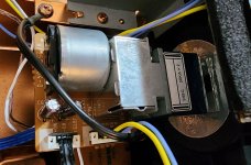
Firstly I done a very simple routing last night by removing the ribbon cable between input PCB to switch direct PCB then use 4 wires to tap signal directly from input PCB to volume control PCB. I like the cleaner/clearer sound but wonder why only right ch get the signal but left is no sound. I attached a rough picture here. I keep looking at the service diagram still doesn't get it why like that. Any other way to do it?
Secondly, even the signal tap directly from input PCB, still need to engage the source direct switch to activate the relay to let signal pass thru the relay. Any other possible way to totally route out the source direct switch?
Eventualy, I confirmed had messed up the wires in my previous attempt. With extra care, I successfully route the signal without going thru the source direct and need not to engage it either.
However, its still suffering left ch softer than right ch hence the center focus is shifted to right. Measuring both output with DVM, left ch do show lower readig then right ch. Do trace this issue, I directing signal from input go straight to the main power PCB, bypassing the volume pot, I am happy to see DVM showed both ch output got same level of set AV. It likely the vol pot is the culprit.
However, its still suffering left ch softer than right ch hence the center focus is shifted to right. Measuring both output with DVM, left ch do show lower readig then right ch. Do trace this issue, I directing signal from input go straight to the main power PCB, bypassing the volume pot, I am happy to see DVM showed both ch output got same level of set AV. It likely the vol pot is the culprit.
Congratulations on your successful wiring...
If you want to isolate the "L channel soft" issue, you swap the current L+ R connections at the INPUT SELECTOR PCB so that R becomes L and L becomes R. This will eliminate/confirm if the issue is occurring before the VOLUME POT.
If it's a VOLUME POT issue, the L channel speaker/headphone output will still be soft.
But before re-arranging the wiring, try using a different input: i.e. AUX, TUNER or CD.
Try rotating the INPUT SELECTOR switch slightly clockwise/counter-clockwise. It may resolve the current issue.
Good Luck!
Thks mate!
I done some further verification by connecting back all the ribbon cable to vol pot back to all original position and did only swapping ribbon cable L+R position to the main power PCB. I happy to see the imbalance level is following this action. Confirmed vol pot is imbalance.
Now I am waiting for the new vol pot to arrive.
