Hello,
discovering i registered in 2013 but never participated at this community, sorry .
As i'm actually trying to repair an amplifier (with kind help of Audio Service member👍 )
i decided exposing here my learning path... may it serve to others and help me succeding at same time...
At switch ON, power red led lights, after 1second relay clicks, 3 blue leds speakers A & B & loudness & red led MUTE goes ON then mute red led goes OFF,
then relay unclick, 3 blue leds go off, power red led flash undefinately > protection mode.
on 14pins main bord connector protect_1 and _2 signals go to 4,97V
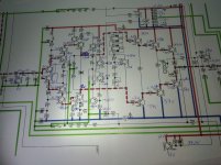
Mesurement power supplies ok, bias to be adjusted later and a BIG DC offset problem Right chanel:
KIA 7805A: IN 24,3V OUT 5,02V
KIA 7812: IN 24,3V OUT 12,05V
KIA 7815A: IN 24,3V OUT 15,08V
KIA 7915PI: IN 24,3V OUT -15,05V
Bias Right: 23mV Bias Left : 32mV
DC Voltage: -2,3Vdc on pin 1-2 Left-CH bias connector to GND and +0,2V on pin 1-2 of Right-CH bias connector to GND
discovering i registered in 2013 but never participated at this community, sorry .
As i'm actually trying to repair an amplifier (with kind help of Audio Service member👍 )
i decided exposing here my learning path... may it serve to others and help me succeding at same time...
At switch ON, power red led lights, after 1second relay clicks, 3 blue leds speakers A & B & loudness & red led MUTE goes ON then mute red led goes OFF,
then relay unclick, 3 blue leds go off, power red led flash undefinately > protection mode.
on 14pins main bord connector protect_1 and _2 signals go to 4,97V
Mesurement power supplies ok, bias to be adjusted later and a BIG DC offset problem Right chanel:
KIA 7805A: IN 24,3V OUT 5,02V
KIA 7812: IN 24,3V OUT 12,05V
KIA 7815A: IN 24,3V OUT 15,08V
KIA 7915PI: IN 24,3V OUT -15,05V
Bias Right: 23mV Bias Left : 32mV
DC Voltage: -2,3Vdc on pin 1-2 Left-CH bias connector to GND and +0,2V on pin 1-2 of Right-CH bias connector to GND
Attachments
For testing (no HP connected because off High DC problem)
i disconnected pin protect2 from main board connector without change, then
reconnected protect2
and disconnected pin protect 1 progress ! no more protection mode, amplifier stays on ready to go.
i measured all this but my knowledge stop here,
please do you see here something which could point me to guilty component(s) ?
thanks
Attachments
Hi Phil916,
Good sleuthing!
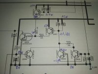
If I understand correctly, you are opening the path to the collector of Q9008 and this disables intervention of protection? Please correct/guide me if this is wrong.
Assuming a correct interpretation, it appears that there are several paths that allow Q9008 to conduct. Would you note voltages at Q9004 through Q9008 is similar manner to your jpg above?
Thanks!
Good sleuthing!
If I understand correctly, you are opening the path to the collector of Q9008 and this disables intervention of protection? Please correct/guide me if this is wrong.
Assuming a correct interpretation, it appears that there are several paths that allow Q9008 to conduct. Would you note voltages at Q9004 through Q9008 is similar manner to your jpg above?
Thanks!

Thanks to you !!!
yes you are right, Pin8 (protect1 signal) disconnected from main board 14 pins connector
sorry here is what i have for the moment,
voltages check is problematic as this part of circuit is also cms under the pcb... without test point 😡
yes you are right, Pin8 (protect1 signal) disconnected from main board 14 pins connector
sorry here is what i have for the moment,
voltages check is problematic as this part of circuit is also cms under the pcb... without test point 😡
Attachments
thanks a lot for your help !
R9005 and R9006 have 0V across them
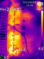
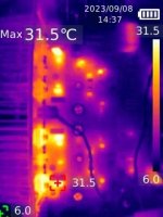
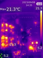
if it helps a friend pasted me a thermal imaging camera
first picture 14 with time stamp 14H32 is power on (with speakers relay switched A-B chanels buttons ON)
seems to me the Right side is hotter few degres more but nothing realy hot, seems no short anywhere
R9005 and R9006 have 0V across them
if it helps a friend pasted me a thermal imaging camera
first picture 14 with time stamp 14H32 is power on (with speakers relay switched A-B chanels buttons ON)
seems to me the Right side is hotter few degres more but nothing realy hot, seems no short anywhere
Attachments

"Mesurement power supplies ok, bias to be adjusted later and a BIG DC offset problem Right chanel:"
BIG DC offset problem si LEFT chanel ! (not Right my mistake)
Hello,
yes as a perfect novice to amps material electronics i tried DC offset adjustement first but potentiometer is out of range to compensate for DC on Left-Ch.
V6003 Left-CH gives -2.65V initial, adjustement range from -2.82V to -2.10V so impossible to go down more than -2.1V full anticlockwise, there is about 3mv consistant difference from readings bias connector pin1-2 to GND and pin3 to GND
V6004 Right-CH gives -0,17V initial, adjustement range from -0,4V to 0,1V, there is about 80mv consistant difference from readings bias connector pin1-2 to GND and from pin3 to GND. exemple setting Vpin 1-2 to GND at -40mv gives 40mv at pin3 to ground.
thank you
This amp has an interesting design. Rather than "voltage feedback", it uses "current feedback", and it has flat gain down to DC rather than rolling the gain off to unity at sub-sonic frequencies. And as we're discovering, it has relatively low offset adjustment range.
I'm beginning to suspect mismatched base currents in Q6004 vs. Q6006, leading to excessive voltage developed across R6010, i.e. the amp input; any voltage there gets amplified by the gain (x 14.2) and appears at the output. Assuming the offset pot is centered, -2.3V at the output corresponds to -162mV, referred to input (RTI). So given this suspicion, would measure the voltage at R6010? Please measure with the meter's most sensitive range--- we would like resolution to mV if possible. Would you also measure the same point in the other channel for comparison?
Thanks.
Last edited:
Thanks for your help and this circuit explanation 👍
with DC offset potentiometers centered:
Left chanel DC offset -2,5V R6009 accross voltage = -9,50mV
Right chanel DC offset -0,1V R6010 across voltage = 4,80mV
with DC offset potentiometers centered:
Left chanel DC offset -2,5V R6009 accross voltage = -9,50mV
Right chanel DC offset -0,1V R6010 across voltage = 4,80mV
work in progress but i already can say i have suspicious variations on common point between Q6017 base Q6021 emeter and D6007
from -35,160 to -35,350V in 10 seconds (and last time i measured max was more at 36,12V)
seems huge to me but i don't now...
and from other measurements from these llast days seems power rail without HP load can go from low 36 to high 37V is this normal ?
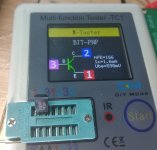
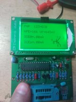
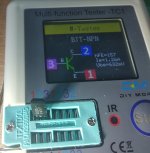
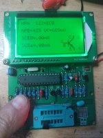
just for information here is Q6019 and Q6033 desoldered results with 2 testers, seems ok though i don't know what to think about differences from tester...
D6015 and D6017 double high speed diodes chip tested: both read 0,61V each diode, 1,22V both chip diode in serie and blocked all other ways.
from -35,160 to -35,350V in 10 seconds (and last time i measured max was more at 36,12V)
seems huge to me but i don't now...
and from other measurements from these llast days seems power rail without HP load can go from low 36 to high 37V is this normal ?
just for information here is Q6019 and Q6033 desoldered results with 2 testers, seems ok though i don't know what to think about differences from tester...
D6015 and D6017 double high speed diodes chip tested: both read 0,61V each diode, 1,22V both chip diode in serie and blocked all other ways.
Attachments
Q6017 base Q6021 emitter are essentially tied near the unregulated negative rail so it would vary with fluctuations in the power-line voltage and I believe you will observe corresponding variation in the positive rail. The amp inherently rejects variation in the supply rails.
I don't see anything obviously wrong with the hfe measurements. I would be suspicious if you saw fluctuation while you measure. Differences between two different instruments I can't explain, but am not too concerned. I'm hopeful that in-circuit transistor terminal measurements may give a clue.
Another experiment I suggest is to connect an expendable speaker(s) so that you can listen to misbehavior. Crackling/ poping noise, or hiss significantly that's large compared to the working channel would be evidence of a leaky component, most likely a transistor. You may have to install a jumper to force the protection relay to energize. You can also put a resistor in series with your test speaker to protect it--- maybe 100 ohm. If you encounter crackling noises, try tapping with a chopstick or similar non-conductive tool--- you might find a mechanically supecptable part.
Hello,
thanks for advise,
If it helps i made signal audio tracer probe with high pass filter (about 15Hz) 95ohms resistor and 100nF to a test point then to an amplified speaker,
... it can help ?
with it i already know there is a problem with volume potentiometer as sound stop here...
but this does not solve the High DC voltage protection mode cause, which is my priority 1
here is voltages of Left chanel with the -2.65V DC at output, measurement to mv scale as requested 😉
I have some tentative suspicions about the amp.
But you mentioned your signal tracer and trouble near the volume control, so a brief detour. There is a mute transistor (Q6001) just in front of the amp input, and I speculate mute might be applied when the amp is in protection. Does your signal tracer reveal any signal at R6003 but suppressed signal at the shunting Q6001 ?
The voltages suggest that feedback is trying to drive Q6007 and Q6011 into conduction and the normal response is that Q6019 collector would pull the driver stages more positive toward equilibrium. But there is large drop across R6043 (compare with voltage R6045) that I suspect may be interfering with correct operation.
In post 11, you examined the adjustment range of the offset trimmers upon the amp output voltage. This time, would you explore how trimmer V6003 affects the collector voltages at Q6023 and Q6025. Compare with the same points in the other channel. They should have similar behavior but I suspect they may be very different.
Thanks.
thanks for your analyse and help ! and first let me say I'm an idiot !
too happy to try for first time my signal tracer i said there was no more sound after volume board... but of course there is no sound .... as i turned the volume potentiometer to 0 ! i know i'm dumb...
so no problem here
there is sound after potentiometer board and there is sound at R6003 and at Q6001 emeter pin, i'm sorry for giving you false paths...
let's forget my 😳 moment please😉
back to real 100% sure problem:
High DC at left Chanel
R6043 read near exact 4,7Kohms same for resistors ok read values nearby
The only resistor nearby which has not right value is R6059, should be 47K and reads 43K !
seems to me this is little out of specs as it should be 47K 5% so 44,65K minimum...
can such low value be my problem ?
mesurement requested
with V6003 full Clock Wise vs anti-CW
Q6023 collector Voltage 11,867 to 16,133v
Q6025 collector Voltage -36,701 to -35,961v
thanks to you !!!
Would you perform the same experiment in the working channel? I expect the reading will be quite different.mesurement requested
with V6003 full Clock Wise vs anti-CW
Q6023 collector Voltage 11,867 to 16,133v
Q6025 collector Voltage -36,701 to -35,961v
- Home
- Amplifiers
- Solid State
- Marantz PM5000 DC offset voltage > protect mode