Hi all,
I am considering simulate one channel of this amplifier in LTSpice. I've been seeing the technical details of this amp and i also want to know more about it.
Here is a link to service manual download:
Marantz PM-80-Mk2 Service Manual, Service Manual, Repair Schematics
The amplifier operates in both classes ( AB and A ). It even has a button to do the switch. What i understand after i saw the service manual is that: when it operates in class A, the voltages in the rails must drop to 24.9v and -24.9v, correct ?

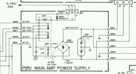
So i can see the power supply providing the correct voltages... :

... But i don't see the power supply providing the 24.9v and -24.9v. And i can see the button to switch classes in the schematic but i don't understand how this circuit works... After all this voltages must come from somewhere, right ?
Or the voltages in the rails, when switched to class A, remain +56.7v and -57v, but what they mean is that they can be reduced to 24.9v and -24.9v if we want, is that it ?
Thanks.
I am considering simulate one channel of this amplifier in LTSpice. I've been seeing the technical details of this amp and i also want to know more about it.
Here is a link to service manual download:
Marantz PM-80-Mk2 Service Manual, Service Manual, Repair Schematics
The amplifier operates in both classes ( AB and A ). It even has a button to do the switch. What i understand after i saw the service manual is that: when it operates in class A, the voltages in the rails must drop to 24.9v and -24.9v, correct ?
So i can see the power supply providing the correct voltages... :
... But i don't see the power supply providing the 24.9v and -24.9v. And i can see the button to switch classes in the schematic but i don't understand how this circuit works... After all this voltages must come from somewhere, right ?
Or the voltages in the rails, when switched to class A, remain +56.7v and -57v, but what they mean is that they can be reduced to 24.9v and -24.9v if we want, is that it ?
Thanks.
Last edited:
Is this a very good amplifier ? It claims to have a very low THD value considering other comercial amplifiers. Would that THD be true ?
Thanks.
Thanks.
Hello
i got the manual from this page
Download Marantz PM-80 Service Manual
If you look at Page 10 you will see the connection to the switch (Class a switch) PSIO (board) JSI2. If you press this Clss A botton the ralay (L851) is switching its 2 conntact and the power transformer provide you the "magic" 17.3V AC -after filtering you get about 20.5VDC.
Maybe in the future this relay contact get worse...so you have to change the relay because the contact ar gone.
regards
chris
Attachments
Last edited:
give it a try
...if you want to pimp this old amp then try to change the PSU electrolytic caps and then the others...first electrolytic.
I did that for my 28 years old Preamp Accuphase C200V and it worked perfectly! Watch out the polarity and the size of the caps in some area !
greetings 😀
chris
...if you want to pimp this old amp then try to change the PSU electrolytic caps and then the others...first electrolytic.
I did that for my 28 years old Preamp Accuphase C200V and it worked perfectly! Watch out the polarity and the size of the caps in some area !
greetings 😀
chris
Thanks guys,
...So if i want to simulate one channel of this amp operating in booth classes in LTSpice, i just have to replace like this:

... and the new switch defines if we want it operating in class A or in class AB ?
Is that it ?
...So if i want to simulate one channel of this amp operating in booth classes in LTSpice, i just have to replace like this:
... and the new switch defines if we want it operating in class A or in class AB ?
Is that it ?
Thanks guys,
...So if i want to simulate one channel of this amp operating in booth classes in LTSpice, i just have to replace like this:
View attachment 656333
... and the new switch defines if we want it operating in class A or in class AB ?
Is that it ?
sorry ..i dont get your point. What do you want with the left drawing? it looks to me like a opto coupler.You want to change this to a switch??
Yes, that opto coupler closes or open the circuit that defines class A or class AB, right ? Can i do it ? ( i mean the repleacement ) ?
Yes, that opto coupler closes or open the circuit that defines class A or class AB, right ? Can i do it ? ( i mean the repleacement ) ?
hmm looks not bad... should work....
but why change the switching function? try in clss A for listening and for party mode release the button😀
Because it would be my first constructed and simulated circuit in LTSpice and i'm afraid i can't found opto couplers in component menu :-D . And i i'm not very experienced with LTSpice also and replace the opto coupler by a switch makes circuit more simple...
Thanks.
Thanks.
Hi, can anyone point me to a link of a tutorial of how to model new transistors for ltspice. I've found this one:
SPICE modeling of a BJT from Datasheet - YouSpice
... it explains how to extract the tansistor details by analising the graphs of the component datasheet ( this is what i want ) ... but, per example, for this transistor, the 2sc3067, the graphs on the datasheet are expressed in other ways ( different from the ones in tutorial ) , and i'm no expert and i am confused and i can't extract the values to use on ltspice. Can you point me in the direction of an alternative of this good tutorial ?
Thanks.
Ive simulated it myself. You dont need to add the "Class A" mode stuff, just leave out R753 and the optocoupler. The relay switches the output stage supplies to a lower voltage in class A mode, thats all.
Hi there, thank you . Really low values of distortion. The value of thd at 10khz is even lower than the value sepcified on the amp specs. Of course the vdc and -vdc in simulation are exact and don't need capacitors, right ? It's different from a power supply, i mean...
Can you still point me in the direction of a tutorial about modeling new transistors for me to make some experiences in ltspice and to learn more ? Preferably by analising the graphs in datasheets ...
Thanks mate.
Can you still point me in the direction of a tutorial about modeling new transistors for me to make some experiences in ltspice and to learn more ? Preferably by analising the graphs in datasheets ...
Thanks mate.
Im afraid Ive never done any SPICE part modelling, and it's a very complex subject. I stick to using manufacturer provided models im afraid!
Can you still point me in the direction of a tutorial about modeling new transistors for me to make some experiences in ltspice and to learn more ? Preferably by analising the graphs in datasheets ...
Bob Cordell's book, "Designing Audio Power Amplifiers" has a useful chapter 20 on Spice modelling, if you can find it.
Brian.
- Status
- Not open for further replies.
- Home
- Amplifiers
- Solid State
- Marantz PM 80 mk2