Hi Folks,
I am a Marantz CD94 user from South Korea.
Could anyone let me know how much the original value of resistors are?
I blew out my beloved CDP by ridiculous mistakes.
It would be really helpful if anybody shows me close-up photos of resistors to read the value.
Lastly, what section is the resistors in? Powersupply or signal path?
Thank you for your help in advance.
Regards,
Kim
Attachments
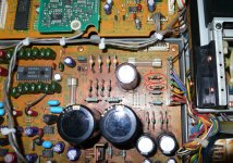
2 resistors are pointed on the image!!
I guess the section is output stage related with OP amp, right?
I guess the section is output stage related with OP amp, right?
Hi!Please can tell me how are called on the PCB?
For example C25 or C followed by a number, if I find I can communicate the value of the wiring diagram.
For example C25 or C followed by a number, if I find I can communicate the value of the wiring diagram.
Hi! Thanks for your reply Tonimxp!
R831,832 are written on the PCB. In addition, I think R801,802 needed to be replaced. Thanks again!
R831,832 are written on the PCB. In addition, I think R801,802 needed to be replaced. Thanks again!
Hi! Thanks for your reply Tonimxp!
R831,832 are wrriten on the PCB.
In addition, I think R801,802 needed to be replaced.
Thanks again!!!
R831,832 are wrriten on the PCB.
In addition, I think R801,802 needed to be replaced.
Thanks again!!!
I had the same problem. These resistors are of a few ohm (3.9 ohm if I remember well) fusible that are blowing out by overcurrent. They are connected between the transformer and both AC sides of the rectifier bridges for the +/-12V and +/-13.5V. The blown resistors on your picture do not seem original. They should not show any burning, just go in open circuit when blown. Since I could not find any replacement, I simply bridged (short-circuited) them. No problem so far...
Thanks Oshifis
Thanks for your kind insturction!
I will try the same way as yours if I can not get the replacement.
There is one more question.
You mentioned the value is 3.9 ohm. Please see the attachment.
R832,831 is marked 1 ohm on the service manual.
Which one is right? I am a bit confused.
If it is just a fuse resistor(not affect to voltage change...)
1 or 3.9 ohm both would be fine,right?
(Sorry for ignorance , I am not an expert...)
Attachments

go to
Philips CD960 | Owners Manual, Service Manual, Schematics, Free Download | HiFi Engine
to download the Service Manual from Philips CD-960.
The differences between CD960 and this model from Marantz is only the outline.
Various threads already exist concerning this both models:
http://www.diyaudio.com/forums/digital-source/89200-help-philips-cd960.html
http://www.diyaudio.com/forums/digital-source/97414-cd960-tray-problem.html
http://www.diyaudio.com/forums/digital-source/20964-philips-cd-960-a.html
http://www.diyaudio.com/forums/digital-source/88286-philips-cd-960-a.html
http://www.diyaudio.com/forums/digital-source/46820-non-oversampling-cd-94-mk1.html
http://www.diyaudio.com/forums/digital-source/5166-looking-marantz-cd-94-schematic.html
http://www.diyaudio.com/forums/digital-source/74783-identifying-cd94-mk2.html
R832,831 is marked 1 ohm on the service manual.
Check my service manual and confirm R832,831 is 1 ohm fusible resistors.
I would check if there are any short on both lines of supply from this two resistors, remove and clean all corroded glue on the circuit board.
Yes it could be 1 ohm, I had only CD94 MkII service manual at hand. Its function might be to limit the initial current surge through the diodes when charging the electrolytic capacitors.Many Thanks Tiefbassuebertr and Fastvideo!
Thanks
Thanks Oshifis!!
Now my CDP is working eventhough I got another problem.
(Coxial digital output doesn`t work after I changed the connector.....)
Thanks for your advice again~~
Thanks Oshifis!!
Now my CDP is working eventhough I got another problem.
(Coxial digital output doesn`t work after I changed the connector.....)
Thanks for your advice again~~
as first step remove the connector lead to the connector and check SPDIF signal with your oscilloskop at the appropriate IC-PIN. Perhaps the high frequency transformer after IC is faulty.
Hi, the SPDIF out is generated on the SAA7220P (the chip closest the rear of the player on the vertical mounted board near the TDA) It drops on to the main PCB via the connector closest to the TDA. You then have some other bits near the connector for the outputs. Follow the servoce manual, but I'm very familiar with this player if you have further questions.
Looking at the picture, you have a TDA1541A S1 crown! Why are you using spdif? I'd be surprised if any external dac would top this TDA when sorted!!!!
Ian
Looking at the picture, you have a TDA1541A S1 crown! Why are you using spdif? I'd be surprised if any external dac would top this TDA when sorted!!!!
Ian
Hi~~
Hiya,
Thanks for your reply.
The reason why using digital output is I am feeling the sound of CD94 is not dynamic enough. I guess need some tweaks on it to make better but I am hopeless at DIY. (That`s why I blew my CD94. I can hardly read schematic.)
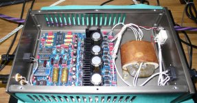
Anyway, you might be curious about my DAC.
The DAC is from analog metric (Made in China).
I didn`t expect much when I got it but the sound was excellent.
It is cheap(around 140 US dollars) but truly worth to try.
Please, see the attached photo how it looks like.
If you want, I can send you high resolution pictures.
Thanks,
P.S Would you mind I ask some help to fix my coxial digital output.
I think I misconnect the unbalaced connector.
Unfortunately, I have no idea how to fix it.
Hiya,
Thanks for your reply.
The reason why using digital output is I am feeling the sound of CD94 is not dynamic enough. I guess need some tweaks on it to make better but I am hopeless at DIY. (That`s why I blew my CD94. I can hardly read schematic.)
Anyway, you might be curious about my DAC.
The DAC is from analog metric (Made in China).
I didn`t expect much when I got it but the sound was excellent.
It is cheap(around 140 US dollars) but truly worth to try.
Please, see the attached photo how it looks like.
If you want, I can send you high resolution pictures.
Thanks,
P.S Would you mind I ask some help to fix my coxial digital output.
I think I misconnect the unbalaced connector.
Unfortunately, I have no idea how to fix it.
Attachments
Hi Pollidel!And sorry if I was not able to respond quickly to the issue of resistors, are glad you solved it anyway. For your problem SPDF output you have to check the connections of PF16 Digital Out pcb is ok, because if it does not powered or disconnected you will not have no digital output on RCA out connector.This is because on this card there is a I.C. that is crossed by the i digital signal and if the card is not connected or not being fed "no output".
Sorry for my English and I hope to be helpful.
Sorry for my English and I hope to be helpful.
Hi!And sorry if I was not able to respond quickly to the issue of resistors, are glad you solved it anyway. For your problem SPDF output you have to check the connections of PF16 Digital Out pcb is ok, because if it does not powered or disconnected you will not have no digital output on RCA out connector.This is because on this card there is a I.C. that is crossed by the i digital signal and if the card is not connected or not being fed "no output".
Sorry for my English and I hope to be helpful.
Sorry for my English and I hope to be helpful.
Hi, I see you are using an S1 Chip in the DAC also!!!! 🙂
R831 and R831 are low ohm fuseible resistors. The value is not crucial but the power rating is. I would replace with something under 5ohms 1/2watt. All they are doing is acting as a fuse! It looks like they have been replaced before!!! To blow like that, I would suggest that there is a short somewhere!
The 5v for the digital out section and the SAA7220 are NOT derrived from the rails on these resistors so the fault is in addition to the servo PSU. What actually happened?? You need to get the servo rails running in order to further fault find the decoder/filter spdif generator.
Those resitors are on the +/-12v rails for the servo section. The -6v rail for the servo and TDA (normally -5v) is also derrived from the -12v rail. The servo regulators on the heatsink on the back of the unit along with themain 5v reg.
I would unplug the heatsink and regs and remove from the unit (effectively isolating the supply. Then replace the fusible resistors and see if they blow again! Assuming not, plug the reg board in and try again.
FYI - it is likely be a fault on one of the rails, and NOT all of them. It could just have been a momentary accidental short to gnd that caused it.
Also, if it makes you feel better, I also shorted one of those rails by accident and needed to replace the resistors!!!! Best of luck Ian
Edit! Also I have built one of those dacs for my music PC! They are very good std but awesome when modded. Not sure I'd want to go through 2 SAA7220P's (CDplayer and DAC unit) myself 🙂
Last edited:
 There was no other broken component inside. I think I have to buy him a soldering iron soon...
- Status
- Not open for further replies.
- Home
- Source & Line
- Digital Source
- Marantz CD94 Help!!!!