Hello!
Been reading through the postings about the Marantz CD63/67 and the noisy power supply lines.
There seems to be a fact that the noise gets worse when Play is pressed. Have seen the laser output myself...brrr...
I have also implemented several of the tweaks in this area with good result.
But all tweaks have more or less tried to cure the symptoms rather that the cause...except for covering the micro processor etc.
Now I wonder: what about silencing the source of all that noise? Where is it? The servo chip? The motor drive? The uProc? Is the crap spread throuhg the air or by the PSu lines backwards? Or have I overlooked a posting somewhere?
Cheers
Tom
The problem is that all the things you name cause the noise! In the CD63 they share a common +5v supply, so each section adds its own noise contribution and makes its own special demands.
All you can do inside the box is attend to using good quality capacitors, ferrites and inductors to decouple the sections from each other. However if you can find space to add separate supplies...then do so, for at least the 3 PSU supplies to the DAC: analogue stage, digital stage and clock (whether you use the Dac's clock stage or an aftermarket one).
I can soon get my CD63 out of storage and make some more specific recommendations if you like.
M.
Hello Martin!
Thanx for your reply...are you the clock mod Martin btw?
I'm on my second CD63 (which I bought very cheap) and I was thinking of trying a "new" approach to the PSU problem.
I will not add an LCClock to this machine, it wasn't successful on the other CD63. The voices moved to the back of the soundstage...but of course I am interested to hear your suggestions - and any other for that matter...
I am wondering, however, which value to use for the chokes instead of the resistors at each section, I used 68uH of the other machine and they have f at 8 MHz or smth...
Cheers,
Tom
The inductors I used were 1mH, with a DC resistance of about 13-14ohms like these . I just used them to replace the resistors at each section. I didn't take any measurements before & after, but the substitution seemed like a reasonable thing to do!
Martin
(yes, that one)
Martin
(yes, that one)
Thanx, what about those: http://www.elfa.se/elfa/produkter/en/2011490.htm
Especially the double...
Cheers,
T
Especially the double...
Cheers,
T
Ferrite beads are very handy, but only affect very high frequency noise (>>0.5 -1Mhz generally) - they will not make a difference you can measure in the audio spectrum. Do try using them though.
Jitter Induced By Servo's? - Guido Tent
Hi Tom & Martin
I would like to direct your attention to a thread I am trying to get going on the influence servo's have on the rest of the system. There is a bit of an overlap with this thread - maybe we can get a usefull discussion started. I'm happy to merge my thread with this one if you think it is appropriate.
Jitter Induced By Servo's? - Guido Tent
Hello!
I will make small 317-based regulators for the analogue and digital suply of the servo chip and see what happens.
Maybe even see what can be done with the motor drive supply etc.
Not a superreg, but quite cheap and easy to make, also used by Martin Clark on the clockmod site...
I am a bit reluctant to throw in the fixed coax at this point as they would make it difficult to disassemble the player.
Cheers,
T
Zombie - that sounds like an excellent idea.
THings that made the biggest difference for me were sorting out the power supplies (especially the 3 to the DAC) changing the output stage opamps to something better (I used AD8620s) and better decoupling all round. The coax is not really worth the hassle.
M.
THings that made the biggest difference for me were sorting out the power supplies (especially the 3 to the DAC) changing the output stage opamps to something better (I used AD8620s) and better decoupling all round. The coax is not really worth the hassle.
M.
Noise suppression
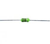
These resistor like chokes (picture) are totally useless at high frequencies due to interwinding capacitance. The ferrite beads Zombie proposes are much better in that respect.
On the other hand one has to ask himself if raising the impedance of the power supply this way is a wise thing to do.
A total rethinking or redesign of the powersupply and it's distribution may be the only right solution.
http://www.diyaudio.com/forums/showthread.php?postid=383227#post383227
(last line)😉
Hi Zombie and Martin,Zombie said:Thanx, what about those: http://www.elfa.se/elfa/produkter/en/2011490.htm
Especially the double...
Cheers,
T
These resistor like chokes (picture) are totally useless at high frequencies due to interwinding capacitance. The ferrite beads Zombie proposes are much better in that respect.
On the other hand one has to ask himself if raising the impedance of the power supply this way is a wise thing to do.
A total rethinking or redesign of the powersupply and it's distribution may be the only right solution.
http://www.diyaudio.com/forums/showthread.php?postid=383227#post383227
(last line)😉
Attachments
Re: Noise suppression
Do radial chokes suffer less from this problem?
Elso Kwak said:
Hi Zombie and Martin,
These resistor like chokes are totally useless at high frequencies due to interwinding capacitance. The ferrite beads Zombie proposes are much better in that respect.
On the other hand one has to ask himself if raising the impedance of the power supply this way is a wise thing to do.
😉
Do radial chokes suffer less from this problem?
Isn't that a bit much resistance? Thorsten, in his TNT audio article, suggests using ones with a low DCR. I used ones that measure one or so ohm, combined with 3 ferrite beads. I think the oringinal resistors measure 10ohms, and I thought we wanted to reduce this. Is there any benefit in keeping this resistance?martin clark said:The inductors I used were 1mH, with a DC resistance of about 13-14ohms...
Dam right! It's one of the few obvious things I've not done yet - I can't see how you could possibly take the main PCB and transport out without breaking something once you've coax'd it all up!Zombie said:I am a bit reluctant to throw in the fixed coax at this point as they would make it difficult to disassemble the player.
Ahh, other replies whilst I was posting, nice 😎
Has anyone implemented a blue LED or two yet? This is something I'd like to try. Powered from a tiny transformer/psu and connected via a plug to the transport, so it's all still removable for 'working'. Maybe one LED per side of the transport? I've seen where I'd try putting them.
I'm not quite Technically-minded enough to work out what traces to cut if adding dedicated psu lines, although I did build an external PSU for my audiocom dvc-1 clock. That was an upgrade I'll not forget!
http://www.elfa.se/elfa/produkter/en/2011490.htm
Wouldn't these be good, R & Z rises at higher frequencies? Isn't the point to have low impedance in the audible range? Most of the crap is HF/RF anyway...
The coax would be the very last thing - or maybe combine it with the contact in some way, when you are happy with the mods you've done (= never)
Wouldn't these be good, R & Z rises at higher frequencies? Isn't the point to have low impedance in the audible range? Most of the crap is HF/RF anyway...
The coax would be the very last thing - or maybe combine it with the contact in some way, when you are happy with the mods you've done (= never)
Zombie said:http://www.elfa.se/elfa/produkter/en/2011490.htm
Wouldn't these be good, R & Z rises at higher frequencies? Isn't the point to have low impedance in the audible range? Most of the crap is HF/RF anyway...
That sounds ideal to me, but don't you mean DC range, not audible range? 😉 (or am I being thick?)
Yep, never! Not as long as there is something more to do, even if that is making all the caps naked (ok, maybe that's too annoying as well!).when you are happy with the mods you've done (= never)
A few days ago I fashioned some smooth blocks of wood from a piece of pine to damp my op-amps (OPA-2604) to introduce a more woody sound (I hoped) but they are way too big to fit in, lol!
Re: Noise suppression
This is what I would like to do in my CD624. As there is a lot of space inside, it would be possible to add a new transformer and dedicated supplies for the DAC, filter, decoder and output stage. This would leave the original analogue stage +/-15V supply available for use elsewhere. I have thought of using it to provide pre-regulated supplies for the other IC's or even for the servo's.
Elso, is this the type of approach you are talking about?😕
Elso Kwak said:
A total rethinking or redesign of the powersupply and it's distribution may be the only right solution.
http://www.diyaudio.com/forums/showthread.php?postid=383227#post383227
(last line)😉
This is what I would like to do in my CD624. As there is a lot of space inside, it would be possible to add a new transformer and dedicated supplies for the DAC, filter, decoder and output stage. This would leave the original analogue stage +/-15V supply available for use elsewhere. I have thought of using it to provide pre-regulated supplies for the other IC's or even for the servo's.
Elso, is this the type of approach you are talking about?😕

- Status
- Not open for further replies.
- Home
- Source & Line
- Digital Source
- Marantz CD63 noise source?