acw said:terminating resistor value
from Thorsten's article
allan (at work)
6h5c said:There's also a piece on coax on the TNT-Audio website, in Thorsten's article, at the end of the digital section.
Regards,
Ray.
😀 I was first 😀
6h5c said:
😀 I was first 😀
that was the third read of thorsten's article before i found the treminating resistors
good read, will go again😀
allan
6h5c
Thorsten is talking about earthinf rf or hf and separating analoge
and digital signal's.
also amazed me when chaned to IEC socket why
first earth the chassis
talking to old valve experts, the ground is the first thing done.
this is working on 100v+ to get rid of mV noise.
to me seems mV noise will have a larger impact on +5v chips.
chassis star earth, earth on IEC socket
shortest distance least resistance to earth
allan
(not at work)
Hey Allan,
Cool article, isn't it? You must know it by head now 😉
8.30hrs : at work
10.02 hrs : not at work
How do you do that? I'd like that job 😀.
If you look at the PSU arrangement: it's asymmetrical. And we put chokes and filters in the supply line, to get rid of noise, and ground is connected....through nothing! The nasty thing is, the ground is reference for all circuits, so the only thing left is create a good star point. At least they did something like that in the player.
In valve-amps the story is a bit different, because most of these circuits have poor PSRR (sometimes only a few dB!), so a few mV on the supply line = a few mV on the output. It would be nice to make something like this in the player:
Ray.
Attachments
that was the end of the day, last hour very quiet.
(left work 6pm)
So we filter before the voltage goes into the circuit.
still need a good earth point preferably away from the analogue(output section)
why not use star earth on chassis then to the IEC socket?
least resistance to earth.
You are the only one i have seen do it.😀
PSRR that explains it.
sound like a bit of tube experience
allan
Stupid me, the time-difference of course 
Why away from the analogue output section? All the PCB signal ground-traces join there, and are connected to the chassis through the RCA connector (J601).
The digital ground is connected to signal ground/chassis through RF57 (22R) (not to be mixed-up with DIG-, which is floating and connected to digital ground by CT03/04), and has a separate trace that runs all the way up, through U205, to the decoder/servo chip. There it is connected to signal ground by U164/165/166.
Note: I noticed that CF51 is shorted by a trace and U233, so it's doing nothing.
Ray.
6h5c said:Stupid me, the time-difference of course
Why away from the analogue output section? All the PCB signal ground-traces join there, and are connected to the chassis through the RCA connector (J601).
The digital ground is connected to signal ground/chassis through RF57 (22R) (not to be mixed-up with DIG-, which is floating and connected to digital ground by CT03/04), and has a separate trace that runs all the way up, through U205, to the decoder/servo chip. There it is connected to signal ground by U164/165/166.
Note: I noticed that CF51 is shorted by a trace and U233, so it's doing nothing.
Ray.
any noise on digital will be harsh on analogue
any noise between digital will affect the clock
eg noise of processor etc
trying to isolate top plan
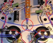
U136, 169. 235, 221, 267
these connect earths to top plan
I think there are a couple of line wires but these are not soldered through?
looking for other components actually soldered througth both top and bottom. cannot find any yet will keep looking🙂
How about caps, havn't taken any out you
all caps are silmic or plan elna, just looked
allan
The top-plane is only connected through the wire-jumpers you mentioned (don't forget U208). Are you going to leave one of them in place, to reference the plane?
There are no soldered through components. The holes in the PCB are not plated through. It's really cheap 😀.
I've taken out/swapped almost all the caps in the analog and digital power supply. If you want to know exactly what I did to my players, take a look at the mods lists at the beginneing of this thread.
Regards,
Ray.
I was just about to post this
This is a double sided pcb, top grd
but it is not plated through😀
Can't find any components soldered on top except those links
I need a magnifying glass😀
allan
ps elna cerafine for opamps
might just add bypass to all caps (except larger power supply caps)
This is a double sided pcb, top grd
but it is not plated through😀
Can't find any components soldered on top except those links
I need a magnifying glass😀
allan
ps elna cerafine for opamps
might just add bypass to all caps (except larger power supply caps)
6h5c said:The top-plane is only connected through the wire-jumpers you mentioned (don't forget U208). Are you going to leave one of them in place, to reference the plane?
There are no soldered through components. The holes in the PCB are not plated through. It's really cheap 😀.
I've taken out/swapped almost all the caps in the analog and digital power supply. If you want to know exactly what I did to my players, take a look at the mods lists at the beginneing of this thread.
Regards,
Ray.
U208🙄
I definitly need better glasses or magnifying glass or maybe even microscope

or just except age and let all go back to valves (i can see them)
i've got U136, 169, 221, 235, 267 so far, will look for 208 thanx
all these earths connect all digital and analogue together then main earth is nuetral?

I'am connecting all earths separately back to star earth Flat brass plate with earth of iec socket?
allan
cd 63 ki and cd57 mods
cd63 ki mkii ,,silver mica black gate and new resistors
and lm 6172
cd 57 same mod
The lm 6172 sounds so good much better than opa2134 and opa2604 🙂
An externally hosted image should be here but it was not working when we last tested it.
cd63 ki mkii ,,silver mica black gate and new resistors
and lm 6172
An externally hosted image should be here but it was not working when we last tested it.
An externally hosted image should be here but it was not working when we last tested it.
cd 57 same mod
An externally hosted image should be here but it was not working when we last tested it.
The lm 6172 sounds so good much better than opa2134 and opa2604 🙂
A question to those who've added separate 5v supplies to the analogue/digital sides of the DAC..
Having looked at the www.acoustica.org.uk site, supplying pin 27 seems easy enough, but I'm not sure how to do the analogue 5v.
If you supply pins 17, 21, 22 and 26 from a single 5v reg, where do you earth it to? The left and right channels have separate earths (joined at the output). Connecting to one or the other may create a loop or compromise channel separation?
Or, do you use a reg per channel, and feed pins 17 and 21 from one and 22, 26 from a second reg?
I'm hoping this mod will aid detail retrieval and transparency, as I've found these areas a bit lacking compared with an Arcam DV29 I've got at home at the moment.
Help much apprieciated
avr300 said:Ingo76, what have you done to the XO ?
/avr300
He just loves his player. Leave him alone.
😀float said:A question to those who've added separate 5v supplies to the analogue/digital sides of the DAC..
---If you supply pins 17, 21, 22 and 26 from a single 5v reg, where do you earth it to? The left and right channels have separate earths (joined at the output). Connecting to one or the other may create a loop or compromise channel separation?
Or, do you use a reg per channel, and feed pins 17 and 21 from one and 22, 26 from a second reg?---
Help much apprieciated
I'd say go for separate regs for left and right channel. The nearest common groundpoint for these voltages would be at the output connector. The ground of the original 5V reg and C815 is nowhere near the DAC, as it runs to the output ground separately. Another idea: use the top-plane?
How did you deal with that Brent?
Regards,
Ray.
6h5c said:
Another idea: use the top-plane?
Regards,
Ray.
Good spot, I forgot to say that earthing the analogue supply to the digital groundplane seemed a bad idea.
6h5c said:......... How does the whipped cream sound? ......
My car is covered in this stuff! I thought it was from the seagulls!
- Home
- Source & Line
- Digital Source
- Marantz CD63 & CD67 mods list