Sorry Badri.
All of the PCB locations for polarized caps will have a circle with a dot indicating where the -'ve pin should go. The vast majority of through-hole capacitors have a stripe on the -'ve side.
If you have a multimeter with a continuity check, you can usually see connection to ground at the striped pin, just to double check. It's sometimes a bit counter-intuitive when dealing with negative supplies because the polarity to ground is reversed, but if you're just swapping components then just keep the stripes on the dots and you should be fine.
Ben
The original CD05 and CD06 are non-polar. Any way around is the correct way as long as you're replacing with non-polar.
Attachments
Last edited:
Thanks Ben, But CD05 and CD06 position is not for electrolytic caps. Its different comes very near to DAC. There I dont find any dots. Hard to identify the polarity sign.
Thanks
Badri
Thanks
Badri
polarity??
Thanks AVR. Can you please tell me in which direction I have to solder the cap?
I am going to use BG STD 220uf there.
Thanks
Badri
The original CD05 and CD06 are non-polar.
Thanks AVR. Can you please tell me in which direction I have to solder the cap?
I am going to use BG STD 220uf there.
Thanks
Badri
Don't you have the service manual ? If not, go to post 1 of this thread, follow the link in Ray's signature to his webpage. Here you will find the manual.
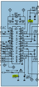
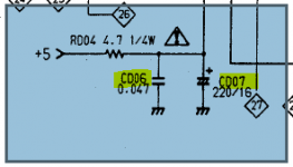
In there you will see that the non-polar is parallel to an electrolytic. If you are to replace the non polar with the BG, forget about the non-polar and replace the electrolytic instead. The electrolytic is marked + and -
In there you will see that the non-polar is parallel to an electrolytic. If you are to replace the non polar with the BG, forget about the non-polar and replace the electrolytic instead. The electrolytic is marked + and -
Last edited:
So, In CD53 CD05 and CD06 is not the one to replace. I am following Ray's Mod list. I think I made a mistake. I removed a wrong component. Please see the below picture. That is what I plucked out from CD05 and CD06.
Thanks
Badri
An externally hosted image should be here but it was not working when we last tested it.
Thanks
Badri
Thanks Ben and AVR300. Now I understood how to replace. But a doubt I have is, Is CD05 and CD06 is the one to replace in CD53? If yes, I will solder BG STD as mentioned by Ben along with help of the image share by AVR300, by pointing the negative side facing to ground. Am I right?
Thanks
Badri
Thanks
Badri
Yes, those are the 47nF non polar caps, CD05 and CD06. Either do:
1. Leave those out and replace the corresponding CD04/CD07 with your BG's
2. Put the CD05 and CD06 back in again and replace the CD04/CD07 with your BG's
1. Leave those out and replace the corresponding CD04/CD07 with your BG's
2. Put the CD05 and CD06 back in again and replace the CD04/CD07 with your BG's
Last edited:
Those are small value ceramic caps. My philosophy has been to replace those with silver mica if practically possible, otherwise leave well alone...
Cd05 and cd06 should be removed allowing cd04 and cd07 to be moved closer to the dac. You can then tag surface mount 100nf across the legs under the board.
Lots of people prefer not to use the 100nf caps when you are using black gates.
The golden rule is to get the caps as close to the pin you are decoupling.
Lots of people prefer not to use the 100nf caps when you are using black gates.
The golden rule is to get the caps as close to the pin you are decoupling.
I thought you'd removed the bypass caps across your BG's Ben?
X7r or c0g or even better PPS would be suitable but I'm not sure I'd use mica on the psu rails??
X7r or c0g or even better PPS would be suitable but I'm not sure I'd use mica on the psu rails??
If you're just starting out, I would stick to swapping like-for-like. You're on very thin ice replacing ceramic caps with Black Gates. My experience has been that Black Gates are a good swap for power supply (especially analogue) if you can get them, and silver mica are great alternatives for ceramic. Mundorf AG are great for PSU and Silver-Oil for signal coupling.
Ian - I've pretty much given up on bypass caps across Black Gates in my system except the main smoothers in my amp which are 80v 10,000uF FK - I have 100v 100uF FKs tagged across those right at the load. I tried lots of other caps there but only the 100v 100uF FKs improved the sound.
I've tried X7R and mica on everything where the mica makes sense, and mica wins in my book. I have bags of Wima and X7R bypass caps sitting around but I'm much happier with the sound without them.
I bought Mundor AG 4700/40v for c803/804. But it is too big to fit. Do you have suggestion to fit those Mundorf in those positions and as well I bought 3300/16v Elna silmic for C814 again the lead is to thick to go inside the hole. Do you have any suggestions?
Thanks
Badri
Thanks
Badri
Previous comment made no sense, sorry - please disregard. Where's the beer smiley?
I haven't used silver micas as bypass caps, but I have swapped all original ceramic caps for micas where possible.
I fitted my Mundorf caps by soldering short lengths of thinner gauge wire onto them (Kimber TCSS)
I haven't used silver micas as bypass caps, but I have swapped all original ceramic caps for micas where possible.
I fitted my Mundorf caps by soldering short lengths of thinner gauge wire onto them (Kimber TCSS)
cap mounting
Drill the pcb with a small drill in a dremel, Thats what i did to mount the pana tsups. 22,000 uf.
😀 alan
The values your using are bit small, larger caps make more inpact on the bass. The machine runs better too.
I bought Mundor AG 4700/40v for c803/804. But it is too big to fit. Do you have suggestion to fit those Mundorf in those positions and as well I bought 3300/16v Elna silmic for C814 again the lead is to thick to go inside the hole. Do you have any suggestions?
Thanks
Badri
Drill the pcb with a small drill in a dremel, Thats what i did to mount the pana tsups. 22,000 uf.
😀 alan
The values your using are bit small, larger caps make more inpact on the bass. The machine runs better too.
Last edited:
- Home
- Source & Line
- Digital Source
- Marantz CD63 & CD67 mods list