Hi all
Can anyone give advice on how to fit those tiny chip caps?
I'm looking to fit 10k0/0.1% at pos RD21-28, i'm not sure my hand is steady enough to just solder 🙁 maybe a drop of superglue?
Cheers Ian
Can anyone give advice on how to fit those tiny chip caps?
I'm looking to fit 10k0/0.1% at pos RD21-28, i'm not sure my hand is steady enough to just solder 🙁 maybe a drop of superglue?
Cheers Ian
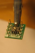
Use tweezers to solder one side, then keep the solder melt (use low power iron) and fit it in line with the tweezers. Here you can solder the other side now that it's hold from one side.
padman said:Hi all
Can anyone give advice on how to fit those tiny chip caps?
I'm looking to fit 10k0/0.1% at pos RD21-28, i'm not sure my hand is steady enough to just solder 🙁 maybe a drop of superglue?
Cheers Ian
Superglue was excellent in this case
Attachments
Ray I will be sending you a C2 to test soon. Could be ideal for testing on the 63 or would it be better to test on your main cdp so that you can test properly
That diy pcb looks good by the way 😉
Brent
That diy pcb looks good by the way 😉
Brent
rowemeister said:Ray I will be sending you a C2 to test soon. Could be ideal for testing on the 63 or would it be better to test on your main cdp so that you can test properly
That's great! I'm looking forward to it. I have plenty of time beginning from next month, so I can do a good PFM Flea - C2 comparison. I will test it in my SA8400, because that's my best player. Make it a 3.3V 33.8688MHz then, if possible 😀.
That diy pcb looks good by the way 😉
Brent
Thanks, I still know how to do it, even though it's been a while 😀
Half the batch is already sold over the weekend...
Ray
The C2 outputs at 2.5V. The C2 requires approx 2 days to run in.
Thats great news about those pcbs
Brent
Thats great news about those pcbs
Brent
OK, cool. I will take enough time to let it settle. Just PM me if you need address details.
Ray
Ray
 is that a typo, or is it 5374 ppm off??
 Help!!
I just made a big mistake
For some reason i had stored 100n x7r caps as the part no for 10k 0.1% resistors
I worked on the drivers, servo, Hf amp and controller had a short listen 😀
In the same way as the last player i got over excited and ploughed on fitting what i thought was the 10ks at RD21-28
The player now wont read the disc... I dont want a 2nd dead player i have no test equipment any ideas very welcome...
Ian
Just switch the parts back to the orig components and it should be ok i would expect.
Do you have a Multimeter?
Lee.
Do you have a Multimeter?
Lee.
I dont know much about service mode but this what i have...
power up p 00
press fwd rwd i can hear the sled try to move makes a clicking sound
press skip p02
sound like something is spinning
press skip p03
the laser moves up/down rapidly
power up p 00
press fwd rwd i can hear the sled try to move makes a clicking sound
press skip p02
sound like something is spinning
press skip p03
the laser moves up/down rapidly
Hi Lee
I changed them back straight away before posting.
What level of multimeter would i need?
Ian
I changed them back straight away before posting.
What level of multimeter would i need?
Ian
Thanks Ray would this do?
Specifications:
Ranges Best accuracy
DC voltage
200mV, 2V, 20V, 200V, 1000V ±(0.5% of reading + 2digits)
AC voltage
200V, 600V ±(1.2% of reading + 10 digits)
DC current
200µA, 2mA, 20mA, 200mA,10A ±(1.0% of reading + 2 digits)
Resistance
200Ù, 2kÙ,20kÙ, 200kÙ, 2MÙ ±(1.0% of reading + 2 digits)
Diode Test
Transistor Test
Ian
padman said:Thanks Ray would this do?
I didn't do anything!? Must be the panic... 😀
- Home
- Source & Line
- Digital Source
- Marantz CD63 & CD67 mods list