Malefoda said:About servo clock, any way to go for the "divide by 2", what it is, how it is and how to do it for cheap with my Flea?
The divide-by-2 will get you results somewhere in between standard and a 2nd dedicated clock.
It's a very fiddly mod to get right and I damaged my player installing it. Be warned - it could cause you grief if you're not confident!
RCruz said:
an you please advise as I would really like to have better bass definition ?
I filled my clamp with hot-melt glue. It made no or very little difference to sound quality. Mine spins off-centre too.
Better bass definition mainly can be had by: replacing the output stage, reclocking DAC & servo and by replacing the feet with cones. The bass should then be stunning.
Simon
Simon, sorry to hear you did't get much out of the clamp mod. Maybe the hot glue hasn't got the mass of blu-tak?
I've now studied Ray's Fully discrete analogue output stage, and it seems fairly easy to implement without any major additional costs. The board layout remains the same, just a few additional passive components in place of the op amps! Can't wait to modify!!
I've now studied Ray's Fully discrete analogue output stage, and it seems fairly easy to implement without any major additional costs. The board layout remains the same, just a few additional passive components in place of the op amps! Can't wait to modify!!
Oh my now I want a discrete output also =)
Anyway I'm gettin nervous as:
the ribbon cable between the main board and the daugther board under the mec is a piece of sshhiitt, I have to move it to make it spin. It does work but sometimes when the CD is recognized and it stop spinning it make a "clic" instead of fade out. Also the ferrite on R165 try to jump cray!
It seems that it occurs when i play with open/close quickly, and not when open or close in a normal use. The CD plays nice.
Is it another problem... in my head?
Hey Delphi,
Yes I don't see why you can't use the original PCB for Ray's output stage (as he did with a '67).
I think you'll have to have one of the input pair legs up in the air to get the resistor onto it, but not rocket science.
The HDAM is a very good discrete op-amp. In its standard configuration it is used as a buffer (voltage follower)with 100% negative feedback. No op-amp sounds great like that.
Also, if you cut the track from the output to one of the input pair (it's obvious which connection if you look at the schematic) you now have an inverting input, and a classic op-amp circuit.
You can see from the CD-6000 schematics how to do this as they use the HDAM as part of the filter, not as a buffer.
A passive filter (like Ray's LCRC) fed into this and you would not require output coupling caps either as the DC is common-mode.
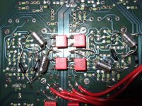
I actually configured my CD67 to use the first half of the IC op-amp as it's used now (LM6172 in my case), and the HDAM as an op-amp for the second stage of the filter. Sounded MUCH better than the standard configuration, but was a nightmare to get all the extra components on the underside of the HDAM without touching the bottom.
In the end I fitted a passive filter followed by an LC-Audio Zapfilter2. It's simply in another league now.
Here's a scary pic of when it had the HDAM as the 2nd part of the filter:
Yes I don't see why you can't use the original PCB for Ray's output stage (as he did with a '67).
I think you'll have to have one of the input pair legs up in the air to get the resistor onto it, but not rocket science.
The HDAM is a very good discrete op-amp. In its standard configuration it is used as a buffer (voltage follower)with 100% negative feedback. No op-amp sounds great like that.
Also, if you cut the track from the output to one of the input pair (it's obvious which connection if you look at the schematic) you now have an inverting input, and a classic op-amp circuit.
You can see from the CD-6000 schematics how to do this as they use the HDAM as part of the filter, not as a buffer.
A passive filter (like Ray's LCRC) fed into this and you would not require output coupling caps either as the DC is common-mode.
I actually configured my CD67 to use the first half of the IC op-amp as it's used now (LM6172 in my case), and the HDAM as an op-amp for the second stage of the filter. Sounded MUCH better than the standard configuration, but was a nightmare to get all the extra components on the underside of the HDAM without touching the bottom.
In the end I fitted a passive filter followed by an LC-Audio Zapfilter2. It's simply in another league now.
Here's a scary pic of when it had the HDAM as the 2nd part of the filter:
Attachments
....sounds like you're going for the Ray circuit on the host PCB. A fine choice I'm sure.
Note the phasing of the inductors that you use - then most hum/noise pickup from any stray magnetic fields will be common-mode and cancelled in the input stage.
Good luck!
Note the phasing of the inductors that you use - then most hum/noise pickup from any stray magnetic fields will be common-mode and cancelled in the input stage.
Good luck!
delphiplasma said:Simon, sorry to hear you did't get much out of the clamp mod. Maybe the hot glue hasn't got the mass of blu-tak?
I believe that if the clamp works off center, adding mass to it might be a bad idea.
i had an odd problem in my standard 63 where it would play commercial CD's fine but any CDR would make an odd whinning noise in the first 30secs of playing and then stop... TOC reading was fine just playing... Brent suggested blutac in the plastic clamp and it worked perfectly - no noise and perfect CDR playing..
adyf said:i had an odd problem in my standard 63 where it would play commercial CD's fine but any CDR would make an odd whinning noise in the first 30secs of playing and then stop... TOC reading was fine just playing... Brent suggested blutac in the plastic clamp and it worked perfectly - no noise and perfect CDR playing..
Hi.
This problem was covered earlier in this thread and also in other threads.
Early mechs were prone to this fault. Marantz produced a cure which was incorporated in later models.
Rather than use blutac, glue a coin (UK 10p ) to the centre - actual centering can be done while the glue is wet. (Marantz used a metal disk)
Andy
Hi,
I did have 2 questions regarding the mod:
1) Is the DC blocking cap required on the output? That seems to have been answered.
2) Can I get away with using the original input FETs, instead of replacing them with 2SK170s? I'm just about to do a data check on both, to see what the 'gain' differences are, but in the meantime if anyone has used the original FET's, please let me know.
Also, a new question. There is a mention of 'The phasing' of the input inductor, How do you go about checking this? Sorry if I'm going over old ground.
I'll also take a look at that CD6000 schematic.
Thanks
If you're going to go with Ray's circuit you DO need the output coupling cap. I was just saying that if you used the HDAM as an op-amp you don't.
I don't know the specs of the original FETs - Ray/Brent may know.
I suspect Brent at least will recommend using 2SK170's no matter what.
You should be able to tell the inductor's polarity either from a marking on one terminal (e.g., a dot on one side) or just from where the wires go off to (i.e., not symmetrical).
If the polarity and physical position of the inductors is the same any pickup should cancel in the input stage.
The worst that would happen is that one or both channels would hum, and then you'd reverse ONE of the inductors on the humming channel. In my case I couldn't eliminate it completely at first - I think I used very cheap inductors - so I replaced them with Toko 10RB shielded inductors (sourced from jabdog) and it went away completely.
Ray's circuit is tried and tested on this forum, so is a safe option.😉
Glenn2 said:I suspect Brent at least will recommend using 2SK170's no matter what.
Oh I don't know... Brent doesn't really believe in quality parts.


Rayregs
Hi Ray
I have just built the external 12v PSU using your regs layout.
I am measuring +12.05V and -12.10V relative to ground.
Can I use this setup to power the LM4562NA opamps ?
What kind of trouble can I expect from this difference in voltages ?
Regards
Ricardo
Hi Ray
I have just built the external 12v PSU using your regs layout.
I am measuring +12.05V and -12.10V relative to ground.
Can I use this setup to power the LM4562NA opamps ?
What kind of trouble can I expect from this difference in voltages ?
Regards
Ricardo
Re: Rayregs
None, the difference is insignificant !!
Andy
RCruz said:
I am measuring +12.05V and -12.10V relative to ground.
............
What kind of trouble can I expect from this difference in voltages ?
None, the difference is insignificant !!
Andy
Thank you Simon
I am using a Nuvotem RS0030P1-2-018 that outputs 20.5 v in each rail so I get 28v out of the diode bridge. hope this gives me more headroom than the stock TX....!!
Ricardo
I am using a Nuvotem RS0030P1-2-018 that outputs 20.5 v in each rail so I get 28v out of the diode bridge. hope this gives me more headroom than the stock TX....!!
Ricardo
RCruz said:I am using a Nuvotem RS0030P1-2-018 that outputs 20.5 v in each rail B]
You haven't specified the current (or power, expressed as Volt-Amps/VA) rating of that transformer so I don't know if it will provide more headroom.
It provides isolation from other circuits, which is in itself useful.
Good luck, solder everything carefully and don't blow it all up like I always do 😉
Simon
RCruz said:Thank you Simon
I am using a Nuvotem RS0030P1-2-018 that outputs 20.5 v in each rail so I get 28v out of the diode bridge. hope this gives me more headroom than the stock TX....!!
Ricardo
That transformer is 30VA and 2X 18V same one I used in mine.
It is spot on 😉
Brent
- Home
- Source & Line
- Digital Source
- Marantz CD63 & CD67 mods list