I'm looking into modding the 2 channel section of my Marantz BD8002. Does anyone have experience in modding these units that could point me in a direction? I've been unsuccessful in locating a schematic. If someone could send me one it would be much appreciated. I'm really looking into replacing and bypassing capacitors on the 2 channel section. How can I measure which ones I can bypass and which ones I need to replace? I'm thinking of using Wima capacitors where I can, and maybe something else (if I need to) for the output capacitors. As I said, any help is greatly appreciated.
I tracked down a copy of the service manual and it pretty much looks like I thought, very straight foreword. Really the only questions at this point are can I bypass the output capacitors and the muting circuit and resistors after them? Where would be the best place to measure offset and how would I go about it?
Attachments
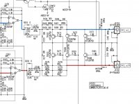
Very bog-standard output stage, as expected. Since it pretty clearly has +/- supplies for the opamps, it should have 0vdc offset(+/- a negligible 50mV), which you'd measure on pin 7 of the two opamps shown. You should darn well be able to jumper out the dc blocking caps, no question. I'd also urge you to ditch those awful Rohm BA15218 chips(an even cheaper clone of the cheap & mediocre Mitsubishi M5218) and replace with OPA2134. Should really improve the overall tone & clarity.
Thank you for the advice. I'm going to go forward with the capacitor and opa mods. When I do the mods I'll report back.
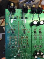
I started my upgrade process today. I was able to remove all the capacitors without any issues. The ics were a little tricky, but with some patience they came off. I installed the new 2134 ics and completed my work around the muting circuit with solid core silver. Just waiting on the remaining Wima capacitors to throw in. I'll report back with impressions and more pics later.
Unfortunately, in the process I lost a capacitor. C163. It looks like a bypass cap, and the data sheet for 2134 doesn't have it. I was thinking of removing the matching one in the other channel? Any thoughts? It's a 10pf across 6 and 7 of the second 2134.
Unfortunately, in the process I lost a capacitor. C163. It looks like a bypass cap, and the data sheet for 2134 doesn't have it. I was thinking of removing the matching one in the other channel? Any thoughts? It's a 10pf across 6 and 7 of the second 2134.
Attachments
That 10pf in the feedback loop is for reducing the gain at very, very high frequencies. It's extremely unlikely they are needed, but there is a tiny chance that it will reduce HF stability of the output stage. Really tiny chance. But the cap is a tiny enough value that it's well in the "can't hurt the sound" range, so, if it's not a major hassle, I'd replace the cap.
I've finished the modifications for the 2 channel section of this unit and I am very happy with the first impressions. Thank you Stephen for your advice. I replaced all the capacitors with silmic II and the smaller ones with Wima and Vishay. The different op amps really cleaned up the soundstage. I haven't really broken it in yet, but I'm already happy with the difference.
I owned one of these units for about 5 years. It was a tremendous unit for music and movies. Even playing MP3's through the SD card slot sounded better than MP3's should sound. I always assumed the output voltage was high on the unit but never tested it.
I have used the 2134 in the past (not in this unit), and it's a great sounding part. However, it seems to lack information when compared to some others.
I have used the 2134 in the past (not in this unit), and it's a great sounding part. However, it seems to lack information when compared to some others.
- Status
- Not open for further replies.
- Home
- Source & Line
- Digital Source
- Marantz bd8002 mods