Im starting this thread just to share my 8B replica build with fellow DIY builders
This is my 8th DIY amp, but my first amp that’s a replica of a commercial product and my first to use an all steel chassis. This post is just about the chassis. I will be adding more posts over the next 6-8 weeks as I make progress.
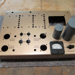
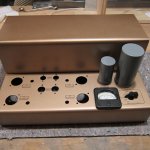
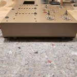
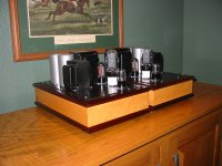
The chassis is made of 3 pieces of 16ga mild steel, and was constructed at home with a DIY bending brake, Greenlee hole punch’s and a step drill bit for the 5/8 and ¾ holes. The sides are silver soldered to the main frame. Solder will not fill gaps, and it’s tricky to solder steel to steel. I used a 1/8 dia brass rod inside the chassis to overcome these two issues.
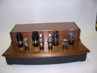
The paint is Rust-Oleum Metallic Rose Gold with a satin clear coat applied after the decals.
The lettering is water-slide decals that where printed with an ink-jet printer.
Yes, I know the original has white text… Most printers don’t use white ink. That’s why used the black text. BTW, I don’t have a real 8B for reference. Everything I’ve done is based on pictures of amps for sale on ebay.
And, why the border around the text you ask? Well on my first attempt I applied the decals without the borders and the thickness of the decal stuck out like a sore thumb. Take a close look at the text on the capacitor… So plan B was the borders.
Of the two pictures posted here, the lower chassis has the clear coat. The transformer cover has not been clear coated yet.
This is my 8th DIY amp, but my first amp that’s a replica of a commercial product and my first to use an all steel chassis. This post is just about the chassis. I will be adding more posts over the next 6-8 weeks as I make progress.
The chassis is made of 3 pieces of 16ga mild steel, and was constructed at home with a DIY bending brake, Greenlee hole punch’s and a step drill bit for the 5/8 and ¾ holes. The sides are silver soldered to the main frame. Solder will not fill gaps, and it’s tricky to solder steel to steel. I used a 1/8 dia brass rod inside the chassis to overcome these two issues.
The paint is Rust-Oleum Metallic Rose Gold with a satin clear coat applied after the decals.
The lettering is water-slide decals that where printed with an ink-jet printer.
Yes, I know the original has white text… Most printers don’t use white ink. That’s why used the black text. BTW, I don’t have a real 8B for reference. Everything I’ve done is based on pictures of amps for sale on ebay.
And, why the border around the text you ask? Well on my first attempt I applied the decals without the borders and the thickness of the decal stuck out like a sore thumb. Take a close look at the text on the capacitor… So plan B was the borders.
Of the two pictures posted here, the lower chassis has the clear coat. The transformer cover has not been clear coated yet.
Attachments
Last edited:
I like this project very much and will follow your progress on this. Like the color too. And black lettering with boarders looks good. I hope you will eliminate any extra screws/holes for small parts underneath because it ruins the look on top. And I'm wondering what output trannies you will use since the originals were special with tertiary feedback windings.
Your sheet-metal working skill is great. Silver solder will flow smoothly if high graded rod is used, provided it's not over heated. I'm familiar to soldering stainless steel tubing to fittings for high pressure instrumentation control.
For joining steel plates, use the normal lead solder but spread it out with a gas torch. It'll filled up every gap and holes.
Nevertheless, your project is superb and I'll be watching it closely.
Thanks for sharing.
For joining steel plates, use the normal lead solder but spread it out with a gas torch. It'll filled up every gap and holes.
Nevertheless, your project is superb and I'll be watching it closely.
Thanks for sharing.
Thank you all the comments.
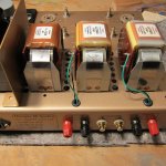
Here's some info on the transformers.
The power transformer is a PA-060-s from triode electronics.
720 V CT @300ma and two 6.3V @5A sections. This is a very nice product... 18" leads.
I'll supply complete details on the power supply later.
For the choke and OPT's I'm planning on using Lundahl iron.
I've always wanted to do a project using Lundahl iron and the 8B is perfect due to it's transformer cover.
The LL1663 OPT is what I have in mind. 5K:8oms with 33% UL
I know it doesn't the special fb winding.... But at $160 each there within my price range and the meet my needs (only 8R output)
For starters, I'm thinking of wiring the EL34's in triode mode. The reason for this is I don't need the full power of UL mode, and based on other amps I've built I think triode mode sounds better....
Last edited:
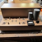
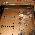
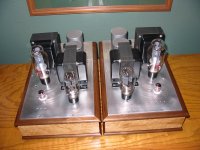
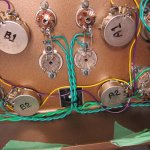
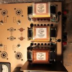
Here are a few more pictures showing close up of the side of the chassis.
To faster the cover to the base, and the feet to the base, I soldered a brass nut to the side pieces. I did this before soldering the sides to the cover. The trick to this is to fasten the nut to the steel with a stainless steel screw to hold the nut in position for soldering..... (5% sliver solder does not stick to stainless steel)
To faster the cover to the base, and the feet to the base, I soldered a brass nut to the side pieces. I did this before soldering the sides to the cover. The trick to this is to fasten the nut to the steel with a stainless steel screw to hold the nut in position for soldering..... (5% sliver solder does not stick to stainless steel)
Attachments
Thank you all the comments.
For starters, I'm thinking of wiring the EL34's in triode mode. The reason for this is I don't need the full power of UL mode, and based on other amps I've built I think triode mode sounds better....
Why don't you make it switchable?
use a rotary switch with a plastic shaft..Then you can switch it all on one switch and its isolated.
Just for interest have you ever tried putting a couple of diodes in the U/L connection? (Electron stream)
Sounds like triode with more power very similar.
http://www.oestex.com/tubes/oes.html
Regards
M. Gregg
Last edited:
Very nice.
Do you by any chance have pictures of your other diy tube amplifiers? It is your thread after all and I am asking only because it will give me an insight to your methods and if these pictures are any indication, old pictures will provide some foresight to this soon to be completed project.
Do you by any chance have pictures of your other diy tube amplifiers? It is your thread after all and I am asking only because it will give me an insight to your methods and if these pictures are any indication, old pictures will provide some foresight to this soon to be completed project.
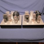
OK, here's the complete history of my amp building hobby (or I should say obsession)
Amp 1, 2A3 mono block
Amp2, 300 Stereo (this is an ugly looking dog)
Amp3, 2A3-40, pentode drivers (this was so ugly I rebuilt it as amp #4)
Amp4, 2A3-40, This was one of my best amps
Amp5, 2A3 stereo with Tube voltage regulator
Amp6, KT88 PP, Stereo My first PP amp, very $$$$ iron
Amp7, C3m-300B Mono Blocks. This is a pentode drive 300p with DC heater's
(It's for sale.... please send private email if interested)
As I mentioned I post#1, the Marantz replica is totally new to me with the all steel chassis and the lettering.
So I've learned a few things along the way....
Stay tuned for an update on the 8B Replica, I'm almost done wiring T1
Attachments
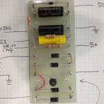
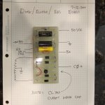
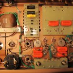
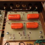
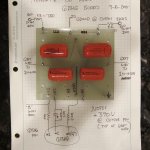
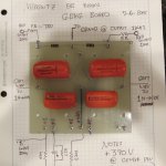
Here are some work in progress pictures of the wiring and add the
diode/bleeder/bias board.
I've add the bleeder for 2 reasons:
1. to drain the capacitors
2. to bias up the heaters to about 42vdc
(as in Marantz Model 9)
This is my first time building turret boards.... It's easy if you have the proper tools (a drill press and a table saw with 1/8 wide abrasive cutoff blade )
I purchased a 6x24 inch sheet of 1/8 thick G10 material from McMaster-Carr and the turrets from Tube Depot. Tube Depot has detailed instructions on how to build "Press Fit" turret boards.
Here's the link...
https://www.tubedepot.com/products/anvil-and-swage-turret-kit
Attachments

Congratulations for your outstanding craftsmanship and meticulous work, this is way above anything I've seen posted on these forums since many years. Keep us posted about your progress. (pictures) When finished, you'll undoubdetly have the most beautiful 8B clone ever built. Hope it will sound as good as it looks...
 Wherever Saul Marantz is, my guess is that he's grinning.
Beautiful woodworking! For amp #6, are those Plitron output transformers?
Yes, amp#6 was with Plitron Iron
I just ordered the Iron and the EL34's for the 8B Replica
With any luck the amp will get powered up this weekend, or next weekend at the latest...
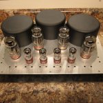
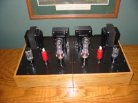
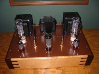
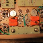
Here's an update with detailed pics of the "6BH6 Turret Board" and the choke and OPT's mounted.
The original 8B layout is an outstanding example of point to point wiring using a minimal about of extra solder joints, and it's laid out symmetrically with a well thought out ground buss.
You may have noticed I'm trying to use the same layout as the original.... Only using turret boards.
I designed the boards to mount using the same hole pattern as the choke/OPT's
I'm pleased to say that the specs sheet's for the iron where correct and everything fits / lines up.
I did all the work up to this point without actually having the iron... It worked out for this project, but I do not recommend this. Have the iron on hand before you start drilling holes in the chassis.
This is still a work in progress... more to come
Attachments
BTW,
THANK YOU ALL FOR ALL THE COMPLEMENTS ON THIS PROJECT
Please excuse me if I don't reply to all of them individually
Believe me that I was really touched and encouraged to keep this up after reading things like:
Congratulations for your outstanding craftsmanship and meticulous work, this is way above anything I've seen posted on these forums since many years.
and
Wherever Saul Marantz is, my guess is that he's grinning
Just to quote a few.... Thanks
- Status
- This old topic is closed. If you want to reopen this topic, contact a moderator using the "Report Post" button.
- Home
- Amplifiers
- Tubes / Valves
- Marantz 8B Replica Build