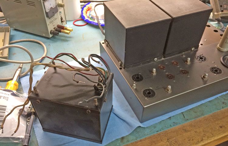
I finally found time to trouble shoot this amplifier. Besides a burned up choke (now rewound), I found the bias winding (-45v) of the power transformer is now open circuit. As you can see from the picture, I have the transformer out and ready to send out for rewinding. 🙁 I assume that when the bias circuit went down, it took out the choke.
I saw the suggestions for rewinders in this thread:
http://www.diyaudio.com/forums/tubes-valves/267808-transformer-rewinding-repair-needed.html
I am leaning towards TRS in Maine, but please feel free to provide suggestions...
Still not 100% sure what caused this. It had all new electrolytics and all the diodes, resistors and np caps still check good. 😕
I did have some intermittent loss of contact on the bias switch when switching between tubes. I have since cleaned this up during this repair process. Kicking myself for not doing this sooner.
I have owned this thing since the early 90's and grown kind of fond of it, so I hope the OPT's aren't damaged. What is the preferred way to see if they are still in good shape? I took DCR for primary and secondary windings and they are basically the same L to R.
L-Primary:
68.1Ω
63.4Ω
27.1Ω screen tap to B+
29.5Ω screen tap to B+
R-Primary:
68.2Ω
63.2Ω
27.0Ω screen tap to B+
29.3Ω screen tap to B+
For some reason the bias winding is known to go open in the 8B power transformer. Something about failed solder joint or similar, I don't remember the exact details. Unlikely that anything you did caused this.
Gary Brown (TRS in Maine) does nice work, he's your man. That 50 year old insulation on the magnet wire failed I suspect, the new winding wire will have far better insulation.
The resistances on the OPTs look fine to me, and the chances of them having absolutely identical failures is pretty close to nil. Those look to be okay.
Good luck with your project!
The resistances on the OPTs look fine to me, and the chances of them having absolutely identical failures is pretty close to nil. Those look to be okay.
Good luck with your project!
The bias winding is the weak spot in more than 1 vintage amp's power "iron". Some "Macs" and the H/K Cit. 2 exhibit the problem too. Mr. McShane has a solution that avoids the considerable expense of a rewind. A small toroid is installed, along with some parts, to take up biasing duties. Whether or not sufficient room is available under an 8B's hood for the toroid is something I can't say.
An AnTek AN-0130 seems electrically suitable. Phase up and series connect the paired secondaries. Bridge rectify and filter.
An AnTek AN-0130 seems electrically suitable. Phase up and series connect the paired secondaries. Bridge rectify and filter.
Thanks for the responses.
Interesting idea to add a seperate supply for the bias. That AnTek is just a shade too big in diameter to fit where the selenium diode was. Is 7va enough for the bias circuit? This toroid is just a bit smaller: http://www.digikey.com/scripts/DkSearch/dksus.dll?Detail&itemSeq=168434042&uq=635619498435518216&CSRT=8555707613065171191
Is this just setting me up for a bigger failure when the next section of the transformer goes out? The power transformer got pretty warm as evidenced by the tar sagging out of the wire hole.
I'd probably just go ahead and get this transformer rewound as you originally planned and avoid further potential issues. These transformers do fail from time to time, HV shorts are not unknown, and if it ran very warm that might be indicative of a problem. (And if you ever do sell it, it will be worth a lot more properly repaired)
Thanks for the responses.
Interesting idea to add a seperate supply for the bias. That AnTek is just a shade too big in diameter to fit where the selenium diode was. Is 7va enough for the bias circuit? This toroid is just a bit smaller: http://www.digikey.com/scripts/DkSearch/dksus.dll?Detail&itemSeq=168434042&uq=635619498435518216&CSRT=8555707613065171191
Is this just setting me up for a bigger failure when the next section of the transformer goes out? The power transformer got pretty warm as evidenced by the tar sagging out of the wire hole.
Leaking tar is BAD news.
 I agree with Dave. Get that power trafo rewound. Adding a toroid is for those situations where only the bias winding has failed and everything else is OK.
A bias supply has to provide but a few mA. Therefore, a 7 VA toroid would be quite sufficient. Unfortunately, the link provided did not work.
When you get the power trafo back, get all selenium rectifiers out of circuit, if not physically removed. Selenium rectifiers are ticking, toxic, time bombs and they must be replaced! I suggest Schottky diodes for their noise free operation. Any time selenium is replaced by silicon, additional resistance is needed to compensate for the change in forward drop.
L-Primary:
68.1Ω
63.4Ω
27.1Ω screen tap to B+
29.5Ω screen tap to B+
R-Primary:
68.2Ω
63.2Ω
27.0Ω screen tap to B+
29.3Ω screen tap to B+
yup, thanks for this very valuable tip.......the choke probably had a much higher dc resistance than your opt primaries, can you post it also? so it is no surprising that it went open first, a good thing since it is easier to get it fixed....
if you lost the bias supply, instead of getting your power traffo rewound which is going to be expensive, i will get another small traffo with a 6.3 volt to 120 volt winding and use that for bias supply....a small traffo can easily be tucked away under the chassis...
in your power traffo, 190 volts ac is fed to the full wave doubler to generate plate B+..
so you have options...
thanks, that's the voice of reason that I needed. I will get it rebuilt correctly.
I took the selenium out of circuit when I replaced the caps. I will go ahead and get rid of it entirely.
I will put a Schottky in the bias supply. Additionally, I saw this suggestion in a different thread (credited to you) in reference to the b+ Supply diodes:
This was from an older thread, so not sure if this would still be your suggestion? Are there any other "improvements" for these amps?
I will be sure to adjust voltages once everything is back together. Speaking of adjusting voltages, would it be a good idea to have the primary windings ratio adjusted to compensate for the higher mains voltages? Or is it safer to stick with the original recipe...
I took the selenium out of circuit when I replaced the caps. I will go ahead and get rid of it entirely.
I will put a Schottky in the bias supply. Additionally, I saw this suggestion in a different thread (credited to you) in reference to the b+ Supply diodes:
Parallel 2X UF5408s with high WVDC 10 nF. caps. and use the assemblies on the ground side of the bridge. Use 2X 600 PIV Schottky diodes on the "hot" side of the bridge. The rail will be dead quiet, while costs are contained. Insert a CL150 negative temperature coefficient (NTC) inrush current limiting thermistor between the Schottkys and the PSU filter, to slightly "soften" B+ start.
This was from an older thread, so not sure if this would still be your suggestion? Are there any other "improvements" for these amps?
I will be sure to adjust voltages once everything is back together. Speaking of adjusting voltages, would it be a good idea to have the primary windings ratio adjusted to compensate for the higher mains voltages? Or is it safer to stick with the original recipe...
with the low prices of silicon rectifiers today, i would think that it is a crime not to replace those seleniums in there...
AJT,
I measure 42Ω DCR and 0.45 H inductance (on a cheap LCR meter). This choke was rewound by a kind member on a different forum who was working on a clone and wanted to find out the wire gauge and # of turns on the original marantz choke. He had some transformer winding equipment to get into winding his own OPT's and I figured a choke should be really easy. Since it was burnt, I was not able to measure it beforehand, so if this doesn't sound like the correct values, please let me know.
Assuming the choke values are correct, the choke does have higher dc resistance than the primaries in parallel = 34Ω
Eli,
Got it, I will keep the inrush limiter on the b+ supply only.
from a rewinding pov, chokes are much easier to figure out, use the same wire size and the same number of turns as the original and all is fine, so i would think he got it correctly, there is no other way for him to do it except follow the original.....i still think you are lucky the choke went first...
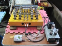
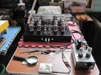
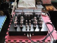
btw, i did a marantz9 wannabe amp last year....
btw, i did a marantz9 wannabe amp last year....
Attachments
I've got a few questions regarding these 8Bs.
I'm asking because I don't know, are all four of the diodes in the
bridge selenium? I was told long ago to replace the bias diode
that it was selenium.
When VAC made their reissue of these amps I was looking for
the replacement caps on the top but from what I was told
they didn't make any extra caps. Any one confirm this?
A local tech also mentioned that I should replace the
bumblebee caps in this amp just to keep the amp running
because with the bumblebees about 1/2 of them fail in
normal operation.
From what I've been told and found out
they are paper caps that were made by Sprague at the time and used
American paper, which wasn't acid free that the European
manufacturers used. This caused the failures.
Also, would it be considered good practice to fit a small
filament toroid in there to avoid the winding failure in
the power trafo?
FWIW, i used a pair of the ON semi, MUR860 rectifiers for plate B+...MUR860: Power Rectifier, Ultra-Fast Recovery, Switch-mode, 8 A, 600 V
yes, for amps pushing years, replacing caps is a good deal...
a small torroid for biasing is what i will do if that were my amp, the wire used for the bias winding used in the original traffo was too small so that it failed with time...
i do my bias psu full wave rectified in my amps...
yes, for amps pushing years, replacing caps is a good deal...
a small torroid for biasing is what i will do if that were my amp, the wire used for the bias winding used in the original traffo was too small so that it failed with time...
i do my bias psu full wave rectified in my amps...
Leaking tar is BAD news.
On the 8B that I reworked, the power transformer had been hot enough to melt a fairly large blob of tar from the opening, and the transformer was still functional. The choke was crispy, and I replaced it with a 5Hy Hammond unit which worked quite well. The amp was blowing fuses on power up and the issue was a shorted OPT winding caused, apparently, by an intermittent bias pot, causing an EL34 to run away. Be sure to clean those well. I replaced the larger can cap with a CE cap from Antique Electronics. To kep the appearance right, I removed and restuffed the voltage doubler caps with modern electros. I replaced the selenium diode with silicon and a resistor and I put new fast recovery silicon in the high voltage rectifier.
5H? seems like mine would measure higher than 0.45H (on LCR meter without any DC bias). Now I am concerned with the rewind job on my choke. 😕
I just pulled the cover off the rewound unit and the core gap is bigger on one side than the other and both sides look bigger than I recall. The winding looks good, but the mismatched gap doesn't give me much confidence. I guess you get what you pay for...
Do you recall the model of the Hammond choke? What is the peak current in this circuit?
I used a Hammond 158Q which fit the existing screw holes and fit perfectly. I dint think the exact value is critical. I no longer have the amp, so I can't measure the current.
Just advice: Clean up those bias pots.
Just advice: Clean up those bias pots.
When measuring these types of chokes...you will need to apply a bit more signal then what you get with a small LCR meter....
In circuit measurement is best and easiest if you dont have acces to a bridge with DC bias.... Measure the AC voltage across the choke and also the AC current in series with the choke.... and use 120Hz as your frequency and you can calculate very simply the henries.. The DC resistance is small enough that it would not need to be vector subtracted...
As for open winding transformers..chances are you don't need a re-wind... I have had many transformers sent to me over the years for re-wind and I am happy to say most of the "open" ones did not not rewinding.. everything from McIntosh OT's to QUAD ...ect... Many times the lead out brakes off from the wire... Durring over-current when the wire does pop...it usually breaks at the inlet to coil... Still need to un-pot the transformer if it is in a can in order to make the repair and not rewind it.... You would place the transformer can on a laboratory HOT PLATE and wait an hour or two till the potting material is loose enough to pour the content out into a steel bucket....carefully and with thick leather gloves and face shiled...
YOu can get away without a bias winding....just tap off the HV winding with series resisitor and diode to feed the bias circuit.... your performance will not be that far off if not the same ...
Last edited:
- Status
- Not open for further replies.
- Home
- Amplifiers
- Tubes / Valves
- Marantz 8b power transformer - open winding