Hi all,
I've finally collected most parts for a modified 7C clone build and have mostly finished with the turret board and tube socket aluminum sheet metal frame.
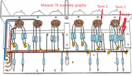
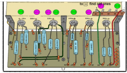
I have a question for anyone familiar with the preamp's circuitry after seeing numerous photos of the circuit board's resistor side. While the original 7C schematic shows a 1M resistor going from grid to ground connected to V1 and V2 terminal #2, after viewing dozens of photos showing the board, the 1M resistor is evident for V1 (R62B) but R62A is missing on V2. Since V1 and V2 are a and b side first stage circuit mirror images, both tubes should show the resistor in the same spot for both tubes but is clearly not the case. Even looking at the 7K kit version instruction guide, the circuit board graphic shows V2 missing R62A. You will see 6 resistors attached to V1 and 5 to V2.
I'm not worried about how I will construct the circuit but is a bit troubling why they would use two different locations for this resistor when all else is symmetrical.
Would love to hear if anyone else has caught this and knows where the mystery resistor is physically located.
I've finally collected most parts for a modified 7C clone build and have mostly finished with the turret board and tube socket aluminum sheet metal frame.
I have a question for anyone familiar with the preamp's circuitry after seeing numerous photos of the circuit board's resistor side. While the original 7C schematic shows a 1M resistor going from grid to ground connected to V1 and V2 terminal #2, after viewing dozens of photos showing the board, the 1M resistor is evident for V1 (R62B) but R62A is missing on V2. Since V1 and V2 are a and b side first stage circuit mirror images, both tubes should show the resistor in the same spot for both tubes but is clearly not the case. Even looking at the 7K kit version instruction guide, the circuit board graphic shows V2 missing R62A. You will see 6 resistors attached to V1 and 5 to V2.
I'm not worried about how I will construct the circuit but is a bit troubling why they would use two different locations for this resistor when all else is symmetrical.
Would love to hear if anyone else has caught this and knows where the mystery resistor is physically located.
Attachments

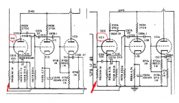
Here's a snip of the original Marantz 7C service manual schematic showing V1 and V2 R62a and b and shot of the Marantz 7K kit circuit board assembly graphic which omits the 1M resistor at terminal 2 of V2 but is included on V1.
To me, no other alternate location makes any logical sense. Hoping someone can help me figure out the anomaly.
To me, no other alternate location makes any logical sense. Hoping someone can help me figure out the anomaly.
Attachments
Not likely to be a mistake, but it may have been located elsewhere due to a ground loop, etc.
The schematic does not document where the parts are physically located, just their connections.
Can you post the entire 7K manual?
The schematic does not document where the parts are physically located, just their connections.
Can you post the entire 7K manual?
Last edited:
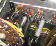
I have the definitive answer. I went to the attic and removed the top cover from one of my Marantz 7s to have a look. The 1 meg CC resistor is mounted on the rear section of the input selector switch. A short (4") length of black coax connects it to the tube. I doubt there is any special reason for this besides convenience.
Attachments
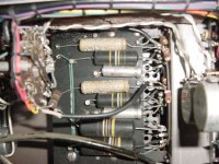
Is it the insulated lead running under the board? I had wondered the same thing but found a photo today showing that it is in fact as hollowstate found looking at his Marantz, insulated lead of the shielded cable from the input selector but I had no idea R62A would reside on the input selector as I assumed it had to be closer to the tube.
Hollowstate, thanks so much for going through the trouble to pull your 7C out and opening it up to discover the answer to my question!
What is still puzzling is why they would feel it necessary to treat V1 differently than V2?
Regarding posting the whole 7K manual. Unfortunately, I was only able to get my hands on a few pages from it where parts of it had been placed in some blog posts covering 7K builds at Naver 동호인과 같이 만들어 보는 마란츠 7 복각 도전 : 네이버 블로그
Attaching another photo and another graphic from the 7K manual
Attachments
- Home
- Amplifiers
- Tubes / Valves
- Marantz 7C Mystery Resistor