This is maybe a newbie question for the experts here, but should help me a lot.
How can I use a scope to properly bias an amp? Particularly the Marantz 2330.
The service manual informs the we have to get 16mV DC between J741 and J742 and so on... But I once heard that using a scope is a more efficient way to measure and adjust it.
Cheers
How can I use a scope to properly bias an amp? Particularly the Marantz 2330.
The service manual informs the we have to get 16mV DC between J741 and J742 and so on... But I once heard that using a scope is a more efficient way to measure and adjust it.
Cheers
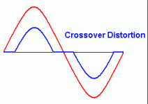
The general way to do it is to put a sine wave on the input of the amp, monitor the output with the 'scope, and then adjust the bias until the crossover distortion notch disappears
The general way to do it is to put a sine wave on the input of the amp, monitor the output with the 'scope, and then adjust the bias until the crossover distortion notch disappears
That's how I do it too.
However some people like a higher bias current as they say it sounds better.
A common setting is 100mA per output pair.
I finds its usually OK at about 10mA which is just as crossover distortion disappears.
... adjust the bias until the crossover distortion notch disappears
Could you explain a little bit.more.of this crossover distortion notch? Also what is the volume pot position? Thank you for the follow-up.
What should the o-scope output look like "when the crossover distortion notch disappears"?
The output should look same as the input which is a sine wave.
Crossover distortion shows up as a kink in the sine wave.
If you turn the bias right down to start with and look at the output will be obvious to you.
Okay, so it's not like clipping where you input a 1 kHz sine wave and adjust a pot until the top and bottom of the wave is "clipped" off on the o-scope.
Thanks for your reply!
Thanks for your reply!
Okay, so it's not like clipping where you input a 1 kHz sine wave and adjust a pot until the top and bottom of the wave is "clipped" off on the o-scope.
Thanks for your reply!
Its just a kink in the sides of the waveform. Nothing like clipping.
You can see it slowly unkink as you turn up the bias slowly.
Google "crossover distortion" and look at the Images section. You'll soon get the idea 🙂
Oh... i also forgot.. you should have the amplifier driving a load for best results. Some 4R7 100W aluminium clad resistors can be used.
Oh... i also forgot.. you should have the amplifier driving a load for best results. Some 4R7 100W aluminium clad resistors can be used.
You should do the bias with a voltmeter instead.
Check here and a few pages in for bias resistor locations.
Marantz 2330 Service Manual (Page 6 of 42)
You adjust bias current be measuring voltage across a resistor that exists between output transistor emitters and the speaker out.
Check here and a few pages in for bias resistor locations.
Marantz 2330 Service Manual (Page 6 of 42)
You adjust bias current be measuring voltage across a resistor that exists between output transistor emitters and the speaker out.
If you don’t have a distortion analyzer use a voltmeter as recommended. The notch is hard to see on just a scope unless it is really off.
If you don’t have a distortion analyzer use a voltmeter as recommended. The notch is hard to see on just a scope unless it is really off.
Thx Wayne, what DA do you suggest with a low price?
A decent sound card and the ARTA measurement software will work. I believe it is a free download. Add an 8 Ohm resistor load and you should be set to go. Be careful and don't bias too high.
The full software unlocked is 79 Euros but still inexpensive and very useful.
The full software unlocked is 79 Euros but still inexpensive and very useful.
Last edited:
On my Marantz 1200, I have to remove the two heatsinks and attach the two DMM (set to DV volts), leads to the two resistors that look like coils on the left side of the board. To adjust bias, I then adjust the pot located close to the center of the board to about 12mVDC.
Marantz 250 power amp board shown- the Marantz 1200/B power amp boards are very similar...
Using an o-scope, I would still need to remove the heatsinks/power amp boards to adjust the pot. Unless the o-scope method is more "accurate," is there any benefit to adjusting the bias on this amp using the o-scope? Either way, I still need to remove the heatsinks to adjust bias.
Attachments

The multimeter method is fine if you are following a manufacturers recommended bias setting. They will have (ideally) determined the bias setting by using a distortion analyser anyway.
It's not efficient for me if I have to remove the heatsinks to adjust bias. DC offset is easy enough to adjust because I can reach the adjustment pot with the heatsink and board in place. I was just wondering if it was more efficient or accurate to use a o-scope to adjust bias. Apparently not. The service manual says to use a VTVM meter to adjust bias and I do not have a VTVM.
You adjust bias current be measuring voltage across a resistor that exists between output transistor emitters and the speaker out.
Sorry but mine is the 2330B, I tried do adjust the bias to 16mv at the two points indicated in the manual but only could achieve with the left channel, on the right nothing changes, the value is also almost 0V, so probably these.measure points are with a cold solder joint or malfunction, where also can I measure it? I looked at the variable trimpot that adjust it and seems ok, 300ohms value. I will try to post some photos to show you guys. DC offset is ok for both, the transistor are not hot, this is why I asked to know the scope procedure for doing it.
A nice weekend to all.
Last edited:
An externally hosted image should be here but it was not working when we last tested it.
Last edited:
- Status
- Not open for further replies.
- Home
- Amplifiers
- Solid State
- Marantz 2330 bias using Scope... How to guide.