Thanks I sure will.You're very welcome. Keep us posted with your progress.
Good luck!
I had bought 20 and they varied widely 452 to 540. I was able to find 2 matched pairs if they can be off by 1. Did find 1 that was exact. Also do these have to be heatshrinked together like originals?buy them in hundreds, then select the best match...0.4 volts is not too far off...
Well I overlooked something earlier. Thought I had eliminated preamp but must have got a fluke measurement. If I plug RCA into main in on back of receiver DC instabilities go away. So guess its coming from preamp. Before I had unplugged preamp from amp directly to make measurement but must have measured wrong side on the relay board before it was fixed.
I had bought 20 and they varied widely 452 to 540. I was able to find 2 matched pairs if they can be off by 1. Did find 1 that was exact. Also do these have to be heatshrinked together like originals?
good, i forgot to mention that matching for Vbe is also good thing aside from hfe match, a dap of silicon grease and heahshrinked together will take care of temperature drifts...
Well I overlooked something earlier. Thought I had eliminated preamp but must have got a fluke measurement. If I plug RCA into main in on back of receiver DC instabilities go away. So guess its coming from preamp. Before I had unplugged preamp from amp directly to make measurement but must have measured wrong side on the relay board before it was fixed.
the electrolytic coupling caps can now be replaced with film types as the film types have gone down in size to fit in the boards....start with the preamp output cap..
The DC instabilities on output are result of preamp not amp. It fluctuactes every fraction of second from 0 to 70mv. Gradually going up or down.So there's drift in preamp--- or it all fixed now?
plastic encapsulated to-92's become noisy over time, i once repaired a Sansui receiver that hissed a lot, so what i did was to replace all to92's regardless that they test good on a tester..
Here's what I've found in preamp so far. The 2 IC's BA312 have stable voltages but have slightly low voltage at pin 6 on both of them. One has 14v and the other 15.5. This board also has 8 tantalum caps where the schematic shows 1 and 3.3 lytics. I know those can go bad over time so will be replacing regardless if bad or not. The 4 transistors have very unstable voltages.-fluctuating just like the DC on amp outputs..
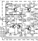
Its Fixed, DC instabilities ended up being the tantalum caps on the Preamp board. Had just 1 more question. I previously replaced 2sa722 with ksa992fta (H701 & 702 the originals handle 100ma and the replacement handles 50ma. Should I put the originals back since they are probably OK or will the current probably never go over 50ma. I know bias is 15ma but will it ever peak past 50 with music?this might help....
https://sparkoslabs.com/ba312-ic-replacements-vintage-audio/
to me the more important specs in that application is hfe, ft, cob....plus Vbe matching too...
you do not need a to92 trannie rated to handle 100mA, when these differential pair run on 1mA collector currents..
these differential pair do not swing voltage like the VAS trannie do, they swing input currents to the base of the VAS..
you do not need a to92 trannie rated to handle 100mA, when these differential pair run on 1mA collector currents..
these differential pair do not swing voltage like the VAS trannie do, they swing input currents to the base of the VAS..
Attachments
Last edited:
Thats great news. Thanks for looking at circuit to determine this.to me the more important specs in that application is hfe, ft, cob....plus Vbe matching too...
you do not need a to92 trannie rated to handle 100mA, when these differential pair run on 1mA collector currents..
these differential pair do not swing voltage like the VAS trannie do, they swing input currents to the base of the VAS..
nothing prevents you from using relatively newer and better silicon devices...having obsolete transistors is not so much pain...
Thats good to know but if the larger transistors ever need to be matched that could get expensive.nothing prevents you from using relatively newer and better silicon devices...having obsolete transistors is not so much pain...
Thats good to know but if the larger transistors ever need to be matched that could get expensive.
output power trannies have local negative feedback for enforcing current sharing, so i am not too concerned...
the VAS and the output trannies swing rail to rail and so must have Vceo specs much grater than the sum of the rails, avoidance of the second breakdown curve of the SOA is to be observed so you do not end up having many many pairs of output trannies....
so close hfe matching of the npn;s and the pnp's is also good but not mandatory.....a close range is okey enough...it is not even required that the npn and pnp power trannies be matched although a close spec is also good.....
the VAS needs special mention, since this is the stage that provides for the maximum ac output swing albeit at low power to be fed the output stage emitter followers.....so high Ft, high hfe and very low cob is the desired parameters, along with the Vceo specs...
today, such trannies are available and more...
- Home
- Amplifiers
- Solid State
- Marantz 2325 has 0.4 to 0.5 volts DC going to relay board on both channels. Any common causes?