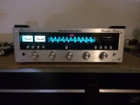
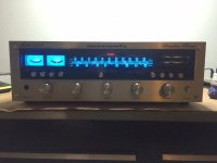
I picked up a nice, clean 2225 last month off CL and it plays/sounds great. Last night I replaced the dial and meter bulbs with blue LEDs from Parts Express. And that results turned out really nice. See before and after pix.
I then set about checking/setting Power Amplifier and Power Supply adjustments and was able to dial in everything except the J712(+)/J718(-) and J713(+)/J719(-) adjustments to 20 mV per the Service Manual. The closest I could dial in was down to 60 and 63 mV respectively. DC offset at speaker terminals is 3 mV and 1.5 mV.
History: Looking over all the boards it is obvious someone has already replaced all the electrolytic caps on all boards, including the amplifier board. And I have yet to verify that all the new caps are properly sized replacements.
So other than wrong cap somewhere, why else might I not be able to dial in the proper 20 mV? Bad trimmer pots maybe?
Attachments
Last edited:
Yikes and gadzooks..... man !!!
These are not power supply adjustments these are the bias adjustments quite critical for the operation and the stability of the amplifier ...
For this amplifier though there is a trick
First you need to verify that a secondary voltage is proper and then try to adjust the bias
if you messed up with other adjustments you are already on the wrong side ...
verify that in the output of transistor H805 at the pin J118 there is exactly 35 volts adjust if needed with variable resistor R808
Then perform bias adjustment and hopefully everything is going to be fine
Though you should look if output transistors are original drivers also If transistors are replaced and probably with some newer types problems like that are expected
Operating this amplifier 3 times the specified bias will produce a lot of heat and eventually end up to stability problems ...
Do some reading also ....
Hi and thanks. I'll check the voltage you mention. I said power amplifier and power supply adjustments as that is how the service manual called them. But I did dial in 35 v supply. I know the 0 and 20 mV are bias adjustments 🙂
I'll check to see if any trannies have been replaced.
I'll check to see if any trannies have been replaced.
So I've checked all the electrolytics that were replaced and found one off. C809 on Power Supply Assy should be 470 uF 16v and I have a 100 uF 100v. Could this lead to higher voltages on the Main Amplifier Assy like I'm seeing?
All the trannies I've looked over appear original.
Also on Main Amp Assy there appear to be two C709 labeled caps. One close to rear that matches C710 and they are both 47 uF. But the other C709 I can't see size as its blocked from my view. It is the large cap in the middle of the board near the top. Does anyone know what label it should have and what size it should be?
There are many mistakes and/or different versions of receivers/manuals in the whole Marantz line up. The test points you measured were for the emitter resistors of the driver transistors, and are close for what you measured. Try measuring J714/16 and J715/17, those should get you to where you want to be. I always check the test points in the manual against the actual unit to see what the hell I'm supposed to be measuring.
Craig
Craig
Hi Craig. J714/16 is 0v. Same with J715/17. Yeah I've seen typos in manuals before. My service manual indicates 470 uF on both the schematic and parts list.
Do the voltages change when you adjust the trimmers? Mark your trimmers before you move them.
Craig
Craig
If you mean R733 and R734, they are both dialed all the way counterclockwise just to get to 60 mV at J712/18 and J713/19. If I turn them clockwise voltage goes up and up on those points. Those trimmers don't seem to effect J714/16 and J715/17.
So I found this thread and see where this guy recapped a 2225 and he had and replaced C809 w a 470 uF cap.
Marantz 2225 Power Supply Post Re-Cap Malfunction Help | Audiokarma Home Audio Stereo Discussion Forums
Marantz 2225 Power Supply Post Re-Cap Malfunction Help | Audiokarma Home Audio Stereo Discussion Forums
C709/10 are the bootstrap capacitors for the driver circuit. They will not affect any DC voltage and will not cause your idle current problem. Replace with what came out of it if they look to be factory installed.
Can you get your probes directly on the output emitters? Or the emitter side of the emitter resistors?
Craig
Can you get your probes directly on the output emitters? Or the emitter side of the emitter resistors?
Craig
I can check them tomorrow. Can you send me labels for the emitter trannies on this guy. H7?? It's a challenge to get at leads with the heat sink in the way but I'll check.
I'll check all tranny voltages according to schematic where voltages are noted.
I'll check all tranny voltages according to schematic where voltages are noted.
I'm not a fan of some those Marantz receivers, especially if the boards are not plug-ins. If you can get to the pins, the base will have approx. .6 volts on it, the emitter "should" be the voltage you're looking for. The case will have the raw power supply voltage on it.
I don't know the orientation of the transistors so I can't tell where each pin will be, right or left.
Craig
I don't know the orientation of the transistors so I can't tell where each pin will be, right or left.
Craig
So I replaced the wrong cap w the right one. Still measured 35 v on power supply board. No change on amplifier board. I'll start checking voltages at each transistor as next step.
First adjust the power supply to 35V.
Then there's the Service Manual error:
You need to measure between J714 and J716; and J715 and J717. Both channels 20mV. (Manual incorrectly states 712/718; 713/719)
Then there's the Service Manual error:
You need to measure between J714 and J716; and J715 and J717. Both channels 20mV. (Manual incorrectly states 712/718; 713/719)
Ah. That helps. Thanks. I guess Craig was trying to point this out as well. I'll check those voltages again tonight.
hey, Easiest way to adjust to dc voltage to zero is to change the resitors on pcb.
If you say turn the varible resitor clock wise and it is linked to a resistor and with common sense you want to turn the resitor more, but you cannont, then change the resitor to a higher value on either side, then you can get zero volts dc.
Also a tip that may be usefull, is that you can put resitors in parallel with the varible resitor, this decreaces the maximum adjustment, so you can fine tune the DC voltage to excactly 0 volts easily
If you are currently running with 1.5mV and 3mV at the speaker, and the amp dosen't blow up after a month of usage, that means your fine. Why bother if the amp runs properly
Last edited:
Tested correct TPs and got 20mV dialed right in. Now have 35v supply and 0/20mV on the amp. All looks good. Thanks everyone. (had similar service manual typo issue w Pioneer SA-8500 a few months back)
hey, Easiest way to adjust to dc voltage to zero is to change the resitors on pcb.
If you say turn the varible resitor clock wise and it is linked to a resistor and with common sense you want to turn the resitor more, but you cannont, then change the resitor to a higher value on either side, then you can get zero volts dc.
Also a tip that may be usefull, is that you can put resitors in parallel with the varible resitor, this decreaces the maximum adjustment, so you can fine tune the DC voltage to excactly 0 volts easily
If you are currently running with 1.5mV and 3mV at the speaker, and the amp dosen't blow up after a month of usage, that means your fine. Why bother if the amp runs properly
You shouldn't do that in this case. If you would have to, then something would be seriously wrong in that amp, and it would need further troibleshooting. No need to change resistor values. Think about it: it left the factory without the mod. Resistors could have drifted. Transistors can have a reduction in gain over time.
I have a Amp and it has 40mV DC at the speakers out of the factory ....... Runs fine even with 40mV
I just checked output at speakers and now have .3 mV right channel, 2.3 mV left channel after setting voltage on correct TPs. I can live with that 🙂
- Status
- Not open for further replies.
- Home
- Amplifiers
- Solid State
- Marantz 2225 Voltage Adjustment Issue