Maybe someone can help me.
the other 2 times that i have mapped impeadance rise i had a working multimeter that could measure AC amperes...well since then the screen has been crushed and it does me no good.
Im not in a financial situation to be spending money, willy nilly, on a $100 clamp on digital ammeter. So i am going to chart my impeadance using an 8ohm 20w non inductive resistor. However, since ive never done it this way before i just did some reading on the internet.
All insturtions say to wire the resistor in series across the terminals or in the electrical line... so i am a little confused. Can someone tell me if the "schematic" below is correct? if so i will be mapping my impedance this weekend and will write up a tutorial and post it in this thread for anyone wondering with pictures if all goes correctly.
well anyway here is the schematic.

Never mind, i asked my dad who was a nuclear engineer in the navy...so of course he knows this simple stuff.
my diagram is correct. and as a matter of fact i am fixingto go chart my impedance right now.
my diagram is correct. and as a matter of fact i am fixingto go chart my impedance right now.

OK, i finished and this is what i came up with.
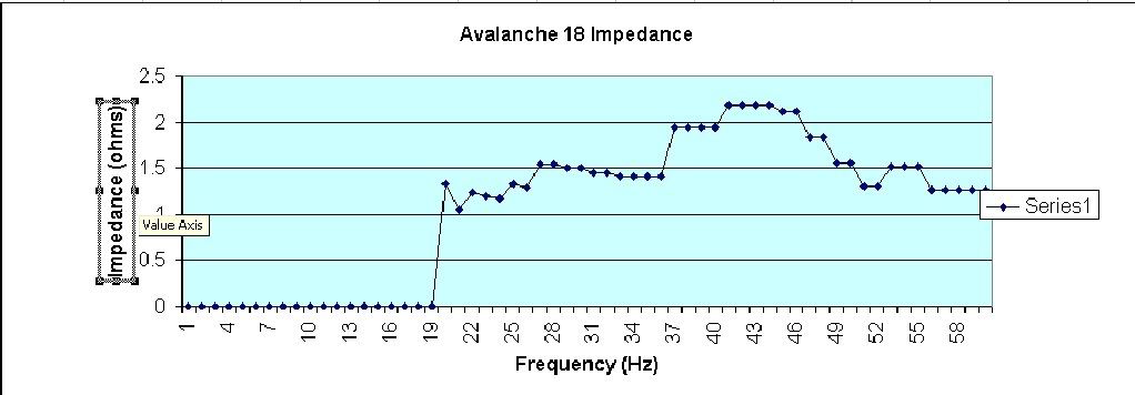
all looks good up untill around 37Hz...big jump in impedance. Could this be where the inductance of the coils actualyl start to take effect?
anyway.
Ok, there arent many places on the internet that tell you how to do this and some done even know what impedance rise is. For some it is just a term wildy thrown about bit thoes retarded audio nerds. Some, when desinging and building an enclsorue, say "im not worried about impeadance rise, yo" and hten end up with less than desireable results.
The fact of the matter is that impedance rise is as important to desireable results, esepecialyl in a ported enclosure, as transient responce and tuning/Qtc.
If you dont know what impedance rise is, with out getting uber technical, just because a driver says "4ohm" doesnt mean that it will always have a 4ohm impedance (impedance is resistnace measured for AC current). Impedance rise is when the impeadance becaomes higher than what the "nominal" imeadance of an inductor is rated as.
Impedance rise can be due to higher enclosure pressures around tuning in a ported/Transmission line/ Bandpass enclosure (any enclosure that is tuned via air ducts). Impeadance rise can be due to the simple rise in frequincy, the higher the frequincy the more suseptible an inductor is to impedance rise. why? because the higher the frequincy the more times per second the electrons have to stop and move in the other direction. the more times you have to do this the harder it becomes for you. same deal. Impedance rise can also be due to a smaller than optimal sealed enclosure. It can be due to the resistance changing as the coil moves though the gap. It can also be directly related to the temperaute rise of the coil as uber ammounts of power are applied; the hotter the metal gets the less the electrons want to move, the hotter your surroundings get the less you want to move.
So, that is all fine and dandy but how do i measure it?
well gather the folowing:
- 10w Minimum non inductive resistor (value doesnt matter)
- 2 VAC's (volt meters, AC current)
- set of tones in the range you want to measure 1hz if you can but 5Hz incraments maximum
- Pen and Paper
-Speaker
-impedance can be measured free air, to check for T/S similarities, however it will change drastically when placed in an enclosre in an evironment. so an enclsoure
-amp and source unit (of course)
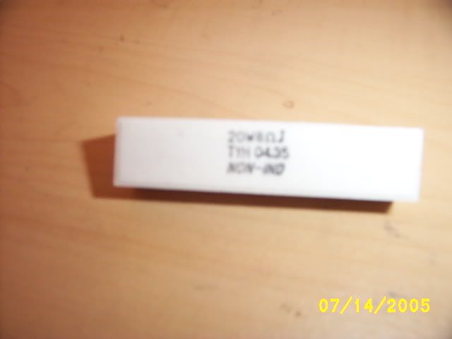
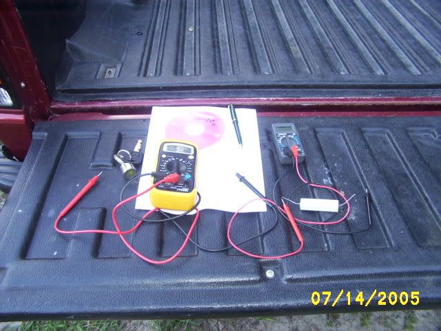
then follow this shematic (coils dont nessicarily have to be in parallel and it doesnt have to be a DVC sub either, just put the resistor in the path of the current so all curent has to pass though it, ie sereis)
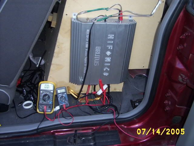
connect one VAC to the output terminals of the amp and one to each side of the resistor and set both to 200v (unless you have a supper high powered system or one with a really high impedance for some odd and rare reason)
so it looks something like this
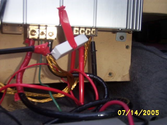
not put your CD in, i did 20-60Hz tones in 1Hz incraments. write down the voltage on both meters (each in its own colum) with what frequincy. KEEP THE VOLUME LOW!!! you dont need to go over 3-4v for any nominal load
Example:
Voltage @ Resistor Voltage @ Terminals
20Hz 3.6 4.2
21Hz 3.8 4.3
22Hz 3.9 4.5
after you do your entire range of what you want to chart go back and enter them into a ploting program (excel works great, so i am using it in my insturctions)
Follow these:
1.) Do each frequincy in the A colom that you used
2.) B colom will be Voltage at the resistor
3.) C colom will be voltage at the terminals and D colom enter the resistance of your resistor
4.) Then for row 1 enter in this formula (C1*(D1/B1))-D1 as your sum for E colom.
5.) Excel will calulate that frequincy's impedance. if yo udid it right it wil make sence...if its 4ohm nominal shount be 23ohms or 0.8ohms.
6.) if its correct copy that formula and highlight all of the remining E colom for your given frequincies and paste that formula into your sum bar. it SHOULD (key word there) calculate all of your impedances for you.
7.) if you want a chart...well ill add that later 😀

all looks good up untill around 37Hz...big jump in impedance. Could this be where the inductance of the coils actualyl start to take effect?
anyway.
Ok, there arent many places on the internet that tell you how to do this and some done even know what impedance rise is. For some it is just a term wildy thrown about bit thoes retarded audio nerds. Some, when desinging and building an enclsorue, say "im not worried about impeadance rise, yo" and hten end up with less than desireable results.
The fact of the matter is that impedance rise is as important to desireable results, esepecialyl in a ported enclosure, as transient responce and tuning/Qtc.
If you dont know what impedance rise is, with out getting uber technical, just because a driver says "4ohm" doesnt mean that it will always have a 4ohm impedance (impedance is resistnace measured for AC current). Impedance rise is when the impeadance becaomes higher than what the "nominal" imeadance of an inductor is rated as.
Impedance rise can be due to higher enclosure pressures around tuning in a ported/Transmission line/ Bandpass enclosure (any enclosure that is tuned via air ducts). Impeadance rise can be due to the simple rise in frequincy, the higher the frequincy the more suseptible an inductor is to impedance rise. why? because the higher the frequincy the more times per second the electrons have to stop and move in the other direction. the more times you have to do this the harder it becomes for you. same deal. Impedance rise can also be due to a smaller than optimal sealed enclosure. It can be due to the resistance changing as the coil moves though the gap. It can also be directly related to the temperaute rise of the coil as uber ammounts of power are applied; the hotter the metal gets the less the electrons want to move, the hotter your surroundings get the less you want to move.
So, that is all fine and dandy but how do i measure it?
well gather the folowing:
- 10w Minimum non inductive resistor (value doesnt matter)
- 2 VAC's (volt meters, AC current)
- set of tones in the range you want to measure 1hz if you can but 5Hz incraments maximum
- Pen and Paper
-Speaker
-impedance can be measured free air, to check for T/S similarities, however it will change drastically when placed in an enclosre in an evironment. so an enclsoure
-amp and source unit (of course)


then follow this shematic (coils dont nessicarily have to be in parallel and it doesnt have to be a DVC sub either, just put the resistor in the path of the current so all curent has to pass though it, ie sereis)
An externally hosted image should be here but it was not working when we last tested it.

connect one VAC to the output terminals of the amp and one to each side of the resistor and set both to 200v (unless you have a supper high powered system or one with a really high impedance for some odd and rare reason)
so it looks something like this

not put your CD in, i did 20-60Hz tones in 1Hz incraments. write down the voltage on both meters (each in its own colum) with what frequincy. KEEP THE VOLUME LOW!!! you dont need to go over 3-4v for any nominal load
Example:
Voltage @ Resistor Voltage @ Terminals
20Hz 3.6 4.2
21Hz 3.8 4.3
22Hz 3.9 4.5
after you do your entire range of what you want to chart go back and enter them into a ploting program (excel works great, so i am using it in my insturctions)
Follow these:
1.) Do each frequincy in the A colom that you used
2.) B colom will be Voltage at the resistor
3.) C colom will be voltage at the terminals and D colom enter the resistance of your resistor
4.) Then for row 1 enter in this formula (C1*(D1/B1))-D1 as your sum for E colom.
5.) Excel will calulate that frequincy's impedance. if yo udid it right it wil make sence...if its 4ohm nominal shount be 23ohms or 0.8ohms.
6.) if its correct copy that formula and highlight all of the remining E colom for your given frequincies and paste that formula into your sum bar. it SHOULD (key word there) calculate all of your impedances for you.
7.) if you want a chart...well ill add that later 😀
- Status
- Not open for further replies.