I am working on a guitar effect that uses a single transistor. A number of transistors have been tested in the circuit and three in particular are producing good results, each with significantly different gain factors.
I am exploring the possibility of building another circuit based on this one but having all three transistors on board and allowing the user to select with a toggle or slide switch. I am currently under the assumption that the only current flow I need to control is that to the base, possibly using pull down resistors to ensure that transistors that are supposed to be off are off. If this is so I would also think a triple throw switch should fit the bill (on-on-on).
Thoughts? Anything I'm missing/overlooking?
Thanks in advance.
My crystal ball is away for repair at present so I can't comment on a circuit I can't see.
A BJT has three legs. Two of them can be used for input, and two can be used for output. Any one of the three can be AC/signal grounded. Can you see why switching the base current may or may not achieve what you want?
A BJT has three legs. Two of them can be used for input, and two can be used for output. Any one of the three can be AC/signal grounded. Can you see why switching the base current may or may not achieve what you want?
Not being rude, just curious: if 3 transistors are different but still all 3 produce "good results" , why don't you just solder one of them there and call it a day?
Can't add anything useful without seeing the schematic, of course.
Just a side note: if different transistors require individual custom biasing, it does not look like a good design.
Normal goal is to design single gain stages (there's not much more you can do with a single transistor) to be relatively insensitive to individual transistor parameters, precisely to be able to make more units, with off the shelf parts, and know they will work without requiring individual tweaking.
ROG designs, which attempt to mimic tube circuits using FETs and not paying attention at all to proper FET biasing, end up needing one trimmer per FET (and wrongly used at that).
Not kidding 🙁
So please post your schematic.
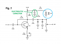
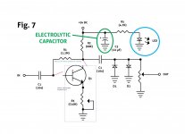
Here is the final schematic from the article from which I am drawing this project.
If one wants to see the whole project with breadboard walkthrough and build instructions the PDF is available here:
http://www.premierguitar.com/ext/resources/files/DIY-PDFs/Oct14_PGDistortion_BuildGuide_Final_R2.pdf
My thoughts are to break the circuit between the junction of the input capacitor and feedback resistor and the pertinent transistor base. All transistors would share the single common collector and feedback resistors.
Attachments
How about just build three of those _circuits_ and switch among the three outputs? You could replicate C1, R1, R2, R3, Q1 and the output 'C1' three times, wire them into a rotary switch, then run that into the diode clipper and the output jack. At the very least, it's simpler to switch a 'normal' signal output than carefully disabling and re-enabling a single transistor stage. And… how expensive are resistors anyway? Not gonna break the bank.
You could do some odd things too, using a footswitch to add each amp output together - it might be fun to use one, two or three of the amps into the clipper - who knows!
Best of luck!
You could do some odd things too, using a footswitch to add each amp output together - it might be fun to use one, two or three of the amps into the clipper - who knows!
Best of luck!
Last edited:
A number of possibilities open up with this circuit. Unfortunately, space limitations forego any unnecessary duplication of parts so a single circuit with allowance for switching between 1 of 3 transistors is the way I am compelled to go. Further down the road some switching capabilities for different diode pairing may be added and would serve more utility. What needs to be remembered is that the target audience on this project is a guitar player and their needs can be quite different from what an electronics purist may want from a circuit. In terms of pedals for inclusion on pedal boards "small" is king.
Well, I am in that business, and there is only so small you can make a pedal. it has to have room for two jacks, a stomp switch, and are there any controls? It needs a battery or at least a power input. Look at the DanElectro series of pedals, They all are mostly the same sizes, and one transistor or 10 transistor fit in the same thing. I might think twice before I buy a large pedal, but those folks at Boss never went broke over the size of all their pedals.
Instead of a switch, you might get somewhere using JFETs or analog switching ICs.
ANother concern is that you are relying on differences between transistors. That is scary, most circuits ought to be relatively free from that. But within that range. If you find that transistor A sounds great at 4 on the control, and transistor B sounds great at 7, you need to step back and listen to both. Does the A at 4 sound like the B at 7? If so, all you have is a difference in setting. In other words, installing a transistor selector switching circuit to replace turning the gain knob, isn't very efficient.
perhaps with a dual pole 3 position rotary switch or sowhat..........
I'm leaning toward a toggle switch if I can. It is usually a smaller footprint and requires less space to operate within. I have some TC Electronics pedals and they postion a three-way toggle switch in the middle of a square defined by four control knobs.
And thank you for the amended circuit. A rotary knob is in consideration but that would be along with a modification that would allow the user to switch between different diode pairings and solely for the purpose of selecting between the pairings.
Last edited:
A switch in the base wire would work for that circuit, provided you are happy to get loud clicks when you switch.
A number of possibilities open up with this circuit. Unfortunately, space limitations forego any unnecessary duplication of parts so a single circuit with allowance for switching between 1 of 3 transistors is the way I am compelled to go.
You do know that the switching stuff will be much larger than the circuit, which BTW, aside from the battery, could probably be built _inside_ of a normal size 1/4" plug. Resistors are tiny my friend, and the largest part there is the pot, which might be a tiny screwdriver trimmer. Next smallest are the two coupling caps, which can be small too.
What needs to be remembered is that the target audience on this project is a guitar player and their needs can be quite different from what an electronics purist may want from a circuit. In terms of pedals for inclusion on pedal boards "small" is king.
I guess I have tunnel vision. I've been working on a tiny, 4 layer SMD, high precision analog board for the past few days, so for me, tiny is getting 14 DPDT switches, 63 resistors, 28 caps, 6 diodes, and a big 100 pin connector into a 1" x 2" board. And, it fits, as long as I have 4 layers to route it!
A stomp box can't even be that small or else it'll flop around on stage, and it seems like I could put about 10-20 of your circuits in the space of a 9V battery.
Not trying to be a jerk, but honestly, switching _one_ transistor in and out of some passives is like switching the transmission in and out of a complete automobile. It's sorta buried in there, right? Especially when your switches are gonna be 5-10x the size of an 1/8W or 1/4W leaded resistor, ignoring positively tiny but high performance SMD parts entirely.
Again, best of luck, and maybe it's good to try it out, see what breaks and then refine it? No harm in building things that don't work… you just try again!
1) the basic circuit is fine, and is somewhat "self adjusting" , because the biasing resistor is connected to the collector.
That said, I've used thousands of those circuits as general purpose gain blocks, I've published Guitar Magazine articles using them from active guitar preamps to 6/8 channel mixers, go figure.
And I often meet Musicians who tell me "hey Juan, I built your mixer 20 years ago ... it's still working like the first day !!!" 🙂
That said, back to practical construction:
1) any switch you add there will be larger than the electronic parts.
2) "all transistors sound the same", they will differ just by gain, which is random within a certain range , factory usually says "between 200 and 500" or something like that, just read the datasheets, so in practice if sound is the same (it is) and only gain varies, that will be accomodated by setting the gain pot , as Enzo said, from 4 to 7 or whatever is needed.
Easier and more finely adjustable than switching transistors in/out
3) now about switching different type diodes in/out , yes, that does bring important changes and is justified.
4) that distortion circuit has very low input impedance, so be certain to use true bypass switching to pull it fully out of the way when not used.
5) any switching involving DC will loudly thump or at least pop.
That gain pot carries DC and will scratch when adjusted.
All this said with the best intention to help, many of us have been along that exact same path .... and we're still here, so it sometimes hurts but never kills 🙂
Pitfall warnings graciously accepted. I'm new at this electronics stuff in general and pedal construction in particular. The thought behind switching the three transistors is to give a guitarist three different gain ranges, with the lower gain having a finer grain control via the gain pot and each gain increase becoming increasingly coarser grained. The particluar transistors in this equation have gain factors of 103, 364 and 758 respectively. The pedal isn't the only factor in the equation. The guitar pickups might be low output single coils or high output humbuckers and I'd like to see if the pedal can easily accommodate some of the differences that alone introduces while trying to attain a certain gain level across multiple instruments. As for the sandpaper from DC in the pot shouldn't be an issue as this is not meant to be adjusted during performance 😛
As I said, I'm new and hoping to have fun as much as hoping to learn a few things. As an earlier poster stated, why not pick one and just build it. For now, that is what is planned as soon as I and my borrowed set of professional ears can decide what the exact final configuration will be.
As I said, I'm new and hoping to have fun as much as hoping to learn a few things. As an earlier poster stated, why not pick one and just build it. For now, that is what is planned as soon as I and my borrowed set of professional ears can decide what the exact final configuration will be.
Well, the "borrowed ears" have already given you a few suggestions to try 🙂
As of the different transistors, that "different gain" looks like a big difference, but it's different current gain; the voltage gain which is what will be heard, will affect distortion, etc. variation will be very little because it depends more on the circuit parameters themselves.
In fact the main control, by far, is the emitter gain pot.
Moving it from ,say, 6 to 7 is more than any change attributable to the transistor.
Now if you want to switch different clipping diodes, that's worth it: Germanium, Silicon, Leds, Zeners, strapped Fets, shorted diode bridges, all clip different.
Post results 🙂
- Status
- Not open for further replies.
- Home
- Design & Build
- Construction Tips
- Manual Transistor Switching