I've been making PCBs for a lot of years now and i thought I'd pass along my favorite ideas and talk a little about problems I've found and how to resolve them.
The system I've settled on is the photo sensitive board process, it makes the finest traces and best overall boards for me. I had a lot of trouble with the positive transparencies used to expose the boards. Originally I used a HP laser printer with transparency film but on double boards I had problems with alignment of the upper and lower traces because, out of the printer, they were not the same size and thus didn't match leaving the holes off from one layer to the next. It may have been my older HP 1100 laser printer but my hunch was that the heat required to etch the printing created dimensional problems in the final transparency. Worse was the drill file that went to my CNC, I could never get the dimensional accuracy for the CNC with laser and the boards would come out drill 'off hole' if the board was over 3 or 4 inches long.
Today I use a HP 8500 inkjet with inkjet transparency film from HP. This works perfectly with exact dimensional stability.
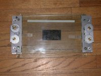
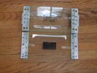
To align my layers I made a jig out of two pieces of 1/4" glass. Each layer is taped to one plate of glass and the two plates are aligned and tightened down. I've included pictures of the frame.
I'm using Eagle now with good results, I previously used Circuit Maker pro but it's outdated. I tried ISIS but it doesn't have the power or accuracy of Eagle in my view.
Etching the boards became a real problem also. I was using the tanks with the fragile aquarium heaters that didn't last. My girl friend, who's a good cook said, "Why don't you try a small crock pot?" It works great, I made a temperature regulator and Lexan holders along with a ring with holes in it for the aquarium pump. Now I can take the ring apart and clean the holes so it never gets clogged like the old tank.
To do vias on my boards I use small pieces of stripped wire inserting the pieces through each small hole and soldering both sides of board. This is the cheapest easiest method I have found so far and the draw back is that I can't run vias under components like capacitors where the leads of the part act as the vias continuity. So in Eagle I restrict top traces on those types of components.
I don't mask or silk my boards so far, I'm looking into methods to do this so if any of you have a good system I'd like to hear about it.
Rob
The system I've settled on is the photo sensitive board process, it makes the finest traces and best overall boards for me. I had a lot of trouble with the positive transparencies used to expose the boards. Originally I used a HP laser printer with transparency film but on double boards I had problems with alignment of the upper and lower traces because, out of the printer, they were not the same size and thus didn't match leaving the holes off from one layer to the next. It may have been my older HP 1100 laser printer but my hunch was that the heat required to etch the printing created dimensional problems in the final transparency. Worse was the drill file that went to my CNC, I could never get the dimensional accuracy for the CNC with laser and the boards would come out drill 'off hole' if the board was over 3 or 4 inches long.
Today I use a HP 8500 inkjet with inkjet transparency film from HP. This works perfectly with exact dimensional stability.
To align my layers I made a jig out of two pieces of 1/4" glass. Each layer is taped to one plate of glass and the two plates are aligned and tightened down. I've included pictures of the frame.
I'm using Eagle now with good results, I previously used Circuit Maker pro but it's outdated. I tried ISIS but it doesn't have the power or accuracy of Eagle in my view.
Etching the boards became a real problem also. I was using the tanks with the fragile aquarium heaters that didn't last. My girl friend, who's a good cook said, "Why don't you try a small crock pot?" It works great, I made a temperature regulator and Lexan holders along with a ring with holes in it for the aquarium pump. Now I can take the ring apart and clean the holes so it never gets clogged like the old tank.
To do vias on my boards I use small pieces of stripped wire inserting the pieces through each small hole and soldering both sides of board. This is the cheapest easiest method I have found so far and the draw back is that I can't run vias under components like capacitors where the leads of the part act as the vias continuity. So in Eagle I restrict top traces on those types of components.
I don't mask or silk my boards so far, I'm looking into methods to do this so if any of you have a good system I'd like to hear about it.
Rob