G'day Guys,
I managed to find a 2KW single phase variac for 100 kiwibucks a wee while back.
https://www.aliexpress.com/item/100...OCdnqQdW&utparam-url=scene:search|query_from:
One of these but without the fuse holder which is problem #1
Problem #2 is the analog meter is pretty poopy. At 230Vac output according to my DMM the analog meter reads 220Vac.
Problem #3 is the connections. Having to wire things in ever time will be a pain in the buttocks.
So my evil plan is to graft a large plastic jiffy box on the front so that I can mount the extra bits to make it more usefull:
Here's the block diagram.
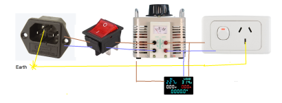
So far I have tested the variac to make sure it works as intended: check.
I checked the accuracy on the built in analog meter as per above. 10Vac out at 230Vac
I also checked the function of the digital meter: much better. 2Vac out at 230Vac
Next up is to start cutting into the jiffy box to mount the goodies.
After that I will need to figure out how to mount the jiffy box to the front of the Variac chassis. Probably rivet nuts.
I managed to find a 2KW single phase variac for 100 kiwibucks a wee while back.
https://www.aliexpress.com/item/100...OCdnqQdW&utparam-url=scene:search|query_from:
One of these but without the fuse holder which is problem #1
Problem #2 is the analog meter is pretty poopy. At 230Vac output according to my DMM the analog meter reads 220Vac.
Problem #3 is the connections. Having to wire things in ever time will be a pain in the buttocks.
So my evil plan is to graft a large plastic jiffy box on the front so that I can mount the extra bits to make it more usefull:
- Fused IEC socket for power in
- A digital meter: https://www.aliexpress.com/item/100...order_list.order_list_main.131.68d61802ltfBqQ
- Illuminated power on switch
- A slimline NZ power socket for the outlet.
Here's the block diagram.

So far I have tested the variac to make sure it works as intended: check.
I checked the accuracy on the built in analog meter as per above. 10Vac out at 230Vac
I also checked the function of the digital meter: much better. 2Vac out at 230Vac
Next up is to start cutting into the jiffy box to mount the goodies.
After that I will need to figure out how to mount the jiffy box to the front of the Variac chassis. Probably rivet nuts.
Make sure the output is fused lower than the input to protect the secondary. If you have a fault large enough to take out the input fuse, it can take out the secondary with it. Besides, are you pulling 2kw through it? At most you should be using a couple hundred watts max just bringing devices up to mains idle, right?
I hadn't thought of fusing the output on the variac.
I was assuming the DUT would have its own fuse but that's not a bad idea.
My thoughts on the input fuse is that it is to protect the Variac not the DUT
The biggest amp I intend to build is a Wolverine.
If the DUT has its own fuse (which it always should), is it still a good idea to have an output side fuse on the variac?
Put another way: Is there a reason that 2 fuses in series is a bad idea. (ignoring the sockets and wire in between)
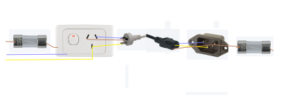
I was assuming the DUT would have its own fuse but that's not a bad idea.
My thoughts on the input fuse is that it is to protect the Variac not the DUT
Correct. I was thinking of something like a 5amp fuse on the input of the variac. That should be more than enough for anything I am building any time soon.At most you should be using a couple hundred watts max just bringing devices up to mains idle, right?
The biggest amp I intend to build is a Wolverine.
If the DUT has its own fuse (which it always should), is it still a good idea to have an output side fuse on the variac?
Put another way: Is there a reason that 2 fuses in series is a bad idea. (ignoring the sockets and wire in between)

No problem with fuses in series. There could be 3-4 fuses in series before your wall socket anyway.
Sure, you're right, if you're always bringing up "complete" fused-inlet DUTs
However, I often use my Variac to quickly bring up unknown (but tested for dead shorts, obviously) transformers on the bench to check ratios and voltages, so having the variac outlet protected by a 2A fuse makes this quick, easy and safer. Also, I just build a quick adjustable DC bench supply with a scrap tranny, some caps and some ammeters straight on the outlet of the variac, because I'm too cheap to buy a bench DC power supply. Again, protected by the fuse in the variac outlet. Also protects the variacs secondary from inrush if you forget to wind the variac down between tests and you have a big transformer hooked up for testing. You don't really know how strong the Variacs secondary is, and you dont want to find out. Fuses are cheap. Cascade the fuses on the variac so its like 5A into the variac and 2A out.
Last edited:
A variac doesn't have a secondary. It has a single winding with an adjustable tap - an autoformer.
No mains isolation.
No mains isolation.
Oh today I learned! Protect the tap then 🤣
It’s more out of industry habit, wherever voltage is stepped down, fuse as close as possible.
It’s more out of industry habit, wherever voltage is stepped down, fuse as close as possible.
Input fuse protects the variac proper from overload. Think "VA total".
Output fuse protects the brush from overload. Think "current". Since you can create a situation at low wiper positions where you easily overload the brush with relatively low input current, the secondary fuse is recommended. It will generally be larger in size than the input fuse, but still works when needed.
Output fuse protects the brush from overload. Think "current". Since you can create a situation at low wiper positions where you easily overload the brush with relatively low input current, the secondary fuse is recommended. It will generally be larger in size than the input fuse, but still works when needed.
I would add a bypass on variac also, lets say you bring up a old amplifier slowly, when you hit mains voltage and no smoke is released you can bypass variac and draw full power , less resistance less inductance, perhaps for a full load test
Last year i took apart my variac, the knob was a bit hard to turn. Contacts and glider were really dirty and corroded, perhaps some arcing occurred, so clean contacts, remember how a bad relay can act up.
Gday guys.
I finally got to fire up the improved variac this evening.
In the end I went with:
The plastic work was not very elegant. The curves on the chassis of the variac were a bit annoying and this is not a show piece so I didn't worry about making things pretty.
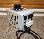
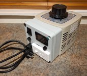
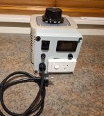
And a wee test. Startup with a dbt and an rcd.
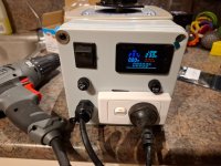
And a crappy drill as a test load
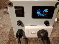
Slow progress for a simple upgrade project but I got there in the end.
At some stage, I will re-engineer the chassis out of some scrap metal and make it look pretty. But my hobby time is severely limited right now so that will probably happen in a decade after this has been used to test all the projects I keep accumulating from this forum.
I finally got to fire up the improved variac this evening.
In the end I went with:
- Fixed power cable
- input fuse
- digital watt meter
- output fuse
- Standard NZ power socket out.
The plastic work was not very elegant. The curves on the chassis of the variac were a bit annoying and this is not a show piece so I didn't worry about making things pretty.


And a wee test. Startup with a dbt and an rcd.

And a crappy drill as a test load

Slow progress for a simple upgrade project but I got there in the end.
At some stage, I will re-engineer the chassis out of some scrap metal and make it look pretty. But my hobby time is severely limited right now so that will probably happen in a decade after this has been used to test all the projects I keep accumulating from this forum.
- Home
- Amplifiers
- Power Supplies
- Making a Variac more optimal
