Hello ,
here is the link to a german homepage with a monster triode amp .
http://home.arcor.de/tubemaster/userprojekte/cool_user_projekts.html
Regards , Alexander .
here is the link to a german homepage with a monster triode amp .
http://home.arcor.de/tubemaster/userprojekte/cool_user_projekts.html
Regards , Alexander .
I first mentioned of this project on another thread called "Where are the 833 amps?"
As anatech mentioned, it would be very hard to find an output xfmer of this power rating with full 20 Hz to 20 KHz fidelity. By lessening the bandwidth requirements it opens the realm of using a high powered plate transformer. The HV windings, say 1710-0-1710 in my case being the plate to plate winding and the 120 volt primary becoming the 8 ohm speaker winding.. Although I have a number of dry plate xfmers about this size collected over the years, only the first one I ever acquired, one I have lugged move to move ever since high school, has sufficient HV winding inductance and test verified fidelity to work as my output xfmer in this project. I sure am glad I kept this heavy beast! Here is my post from the other thread.
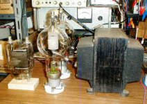
The dry Hammond power supply plate xfmer I have for this project is 2000-0-2000 V and rated at 2.25 kVA. Primary is 230 volts which will be the mains input of this amp. You can only get 1800 watts from a Canadian 115 volt, 15 amp outlet. I need twice this. The core is almost exactly the same size as this one which I'm using for an output xfmer. The picture below shows two 450TH's, my output xfmer and an 833A.
Full wave bridge choke input (LC) filter is planned. These can be pretty smooth. This avoids the need for active voltage stabilization, a big hassle at these voltage and power levels.
As anatech mentioned, it would be very hard to find an output xfmer of this power rating with full 20 Hz to 20 KHz fidelity. By lessening the bandwidth requirements it opens the realm of using a high powered plate transformer. The HV windings, say 1710-0-1710 in my case being the plate to plate winding and the 120 volt primary becoming the 8 ohm speaker winding.. Although I have a number of dry plate xfmers about this size collected over the years, only the first one I ever acquired, one I have lugged move to move ever since high school, has sufficient HV winding inductance and test verified fidelity to work as my output xfmer in this project. I sure am glad I kept this heavy beast! Here is my post from the other thread.
rcavictim said:Just finished listening to this very big hunk-o-iron clip leaded into a pair of 6L6's in a Eico HF-20 monoblock amp. This sounds as good as a REAL output xfmer (I'm talking full range listening on my big 8 ohm lab test speaker stack) and at WOT, (about 24 watts on this amp) the bass extends clean and flat to 10 Hz where my HP generator stops, better waveform than the actual eico output xfmer below 20 Hz. This confirms my earlier microwatt level testing of this big xfmer which looked very promising. The HV winding measures 35 Hy's and 60 ohms DCR plate to plate. Z Ratio is 8 ohms to 7k ohms plate to plate.
Just for a reality check I tried another big plate xfmer which is the same ratio and voltages, but which had much less Primary L (only 20 Hy's) and didn't measure as well on instrument testing. It sounded like absolute junk and the bass response was poor.
Here is a pic of my one prized piece of output iron, all ~100 lbs of it, a pair of 450TH's and an 833A for scale.
When I get started on this project I'll give ity it's own thread.
I wonder what I'll use as a P-P to P-P interstage xfmer?
This will be a fun project! 😀
The dry Hammond power supply plate xfmer I have for this project is 2000-0-2000 V and rated at 2.25 kVA. Primary is 230 volts which will be the mains input of this amp. You can only get 1800 watts from a Canadian 115 volt, 15 amp outlet. I need twice this. The core is almost exactly the same size as this one which I'm using for an output xfmer. The picture below shows two 450TH's, my output xfmer and an 833A.
Full wave bridge choke input (LC) filter is planned. These can be pretty smooth. This avoids the need for active voltage stabilization, a big hassle at these voltage and power levels.
Attachments
I'm getting closer to a design. I have come up with a plan to directly drive the 450TH grids with a pair of cathode follower power tubes, either 810 triodes, or 4-125A beam tetrodes with G1 and G2 strapped together as a triode. Voltage supply for the drivers will be the 1700 VDC supply half tap available as the CT of the master plate xfmer. I therefore need a driver tube that can handle more than 1.7kV on the plate. The 805 unfortunately is not spec'd quite this high at 1500 volts max. I like this arrangement as it save building a third B+ supply for the amplifier just for the drivers. It wastes a hundred watts in the driver tubes though and requires more expensive driver tubes.
The driver cathodes will each hang on the ends of a center tapped 'modulation' choke with the CT grounded (to the output tube neg grid bias supply).
I have just finished making this mod choke. It weighs 13 lbs and has ~320 Hy's end to end. From center tap out one side is 82 henries, CT to the other is 85 henries. DCR is about 200 ohms from each end to CT.
This arrangement will allow me to operate the output stage in pure class A, AB1 or even AB2.
I may tie the mod choke CT to ground and rely on self cathode bias via dropping R for the output tubes. This would allow easy implementation of variable power control by varying the master B+ supply. It would make class AB2 unavailable however. I suspect AB1 is where I'll want to park this anyhow once done. The 450TH's NEED to anode glow or they won't getter, or look as awesome. 😉
- Status
- Not open for further replies.