I was recently gifted a Hafler IRIS pre-amp (along with a DH-200 amp). Unfortunately it does not have a remote control.
Remotes are rare and expensive. In addition one requires the internal receiver board. Cost could be $120 or more if I could find them.
I have studied the IRIS schematic and have decided to roll my own IR remote control.
My plan is as follows.
I'll be using one of these remote kits for arduino.
https://www.ebay.com/itm/373765651681
I will then interface this to an Arduino Pro micro (5v version)
I only plan to implement volume, and input selection at the first go. But I may add balance and normal/mute functionality later on.
Below is what I have figured out so far regarding the interface from the IR receiver board to the pre-amp. This connector is on the back of the display panel of the unit.
In addition there is a transparent window where the receiver phototransistor would mount near the connector.
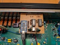
I will mount the Arduino board on perf board and there will be an LM324 to translate the D/A output of the Arduino to create the volume/ balance 0-14v control voltages.
There will also be some 5v to 16v logic translation for the input mux and other control signals.
My first experiment will be to hook up some potentiometers and dip switches to see if I can fake the operation manually.
I will post progress in this thread. All comments and suggestions welcome.
Wish me luck...
Hafler Remote connection
Pin Name Notes
1 JAM I believe JAM is used to lock input selection when recording.
2 RMB 0-14 volts for balance setting from remote
3 RMV 0-14 volts for volume setting from remote
4 REM V/B Active high pulse to set volume, active low to select balance
5 Neg16v
6 NORM Active high pulse to select normal remote
7 MUTE Active high pulse to select mute remote
8 WARN ??
9 Pos16v
10 GROUND
11 N/C
12 I2 "C" select for Input MUX
13 I1 "B" select for Input MUX
14 I0 "A" select for Input MUX
15 I3 Believe this is pulsed high to latch the LED indicator for input and latch selection
Remotes are rare and expensive. In addition one requires the internal receiver board. Cost could be $120 or more if I could find them.
I have studied the IRIS schematic and have decided to roll my own IR remote control.
My plan is as follows.
I'll be using one of these remote kits for arduino.
https://www.ebay.com/itm/373765651681
I will then interface this to an Arduino Pro micro (5v version)
I only plan to implement volume, and input selection at the first go. But I may add balance and normal/mute functionality later on.
Below is what I have figured out so far regarding the interface from the IR receiver board to the pre-amp. This connector is on the back of the display panel of the unit.
In addition there is a transparent window where the receiver phototransistor would mount near the connector.
I will mount the Arduino board on perf board and there will be an LM324 to translate the D/A output of the Arduino to create the volume/ balance 0-14v control voltages.
There will also be some 5v to 16v logic translation for the input mux and other control signals.
My first experiment will be to hook up some potentiometers and dip switches to see if I can fake the operation manually.
I will post progress in this thread. All comments and suggestions welcome.
Wish me luck...
Hafler Remote connection
Pin Name Notes
1 JAM I believe JAM is used to lock input selection when recording.
2 RMB 0-14 volts for balance setting from remote
3 RMV 0-14 volts for volume setting from remote
4 REM V/B Active high pulse to set volume, active low to select balance
5 Neg16v
6 NORM Active high pulse to select normal remote
7 MUTE Active high pulse to select mute remote
8 WARN ??
9 Pos16v
10 GROUND
11 N/C
12 I2 "C" select for Input MUX
13 I1 "B" select for Input MUX
14 I0 "A" select for Input MUX
15 I3 Believe this is pulsed high to latch the LED indicator for input and latch selection
One thing not quite apparent in the IRIS schematic is how the pre-amp "remembers" the current input selection.
On the IRIS you have just momentary push buttons for each of the inputs. You press "AUX1" and the LED above the AUX1 button lights up and that input is selected to the line amp.
The thing is that there is no CPU on the IRIS. There is no RAM either.
It took me a while looking at the schematic before I finally figured it out. It is basically the MUX self driving itself for the input you select through the clever use of diodes. Very entertaining stuff.
The reason I am digging into this as it has to do with how I am going to interface the Arduino to the MUX lines. Both ways have to work. You can select an input on the pre-amp OR you can select an input from the remote.
All the lines on the "MUX bus" are all pulled low via 270k resistors. My plan for interfacing the MUX was to drive some 2n3904 with the 5v logic of the Arduino output pins and these would all have 16v on the high side. Just need to make sure the rest of the IRIS circuit will still work with this arrangement when I turn off the transistors. I think I will run this in the circuit simulator to make sure.
More interesting info...
Need to correct above...
4 REM V/B Active high pulse to set volume, active low to select balance
to...
4 REM V/B Active high pulse to select remote volume and balance.
Again this is a very interesting circuit that latches state as to whether the Pre-amp volume and balance potentiometer voltages are utilized versus the remote voltages.
What is interesting is the dv/dt opamp circuit that is attached to the volume and balance pots. As soon as you turn either on the pre-amp the remote volume/balance voltages are de-selected.
It is pretty cool to see how things were done when an embedded CPU was not utilized. Everything was done with a combination of analog computing with a good dose of diode logic. The CMOS parts used are not really logic parts so much as they are latches and switches. You almost get the feeling that everything could have been implemented with relays if that was all available to Hafler at the time!
So.. it looks like the Arduino code will have to toggle the REM V/B line before inc/dec'ing the volume or balance voltages.
Just to be clear the Arduino IR remote kit that I am getting has up, down, left, right buttons. Naturally I will use the up/down for volume and the left/right for balance. It is not clear to me if the remote will generate a repeating pulse if the buttons are held down. I'll cross that bridge when the remote kit gets here.
BTW, my remote kit is coming from China. I now see Amazon has a similar kit for a little more money. Should have went for that instead.
Also I forgot to include the following connections to the remote board
16 Tuner Light feedback into IRIS IR Remote board
17 CD Light feedback into IRIS IR Remote board
I don't know why the IRIS IR remote board needed this information but I don't believe it relevant to this remote implementation.
Please continue to post your updates; at least one person is reading.
😉
I borrowed a Hafler 915 years ago to play with. I was impressed enough with it that I threw together a quickie version of it to hold me over while I was tinkering around with my primary preamp. It's essentially same as what I saw in your IRIS schematic - CMOS analog switch with JFET buffers. Hafler used a simple diode matrix to select inputs though the 4051. I guess he could advertise back then that the product had no microcontroller generated EMI.
😉
Adding remote capability might be nice .... hmmm ....
mlloyd1
😉
I borrowed a Hafler 915 years ago to play with. I was impressed enough with it that I threw together a quickie version of it to hold me over while I was tinkering around with my primary preamp. It's essentially same as what I saw in your IRIS schematic - CMOS analog switch with JFET buffers. Hafler used a simple diode matrix to select inputs though the 4051. I guess he could advertise back then that the product had no microcontroller generated EMI.
😉
Adding remote capability might be nice .... hmmm ....
mlloyd1
Prototype is almost done. I won't have the IR hardware for a while, but I don't need that to develop the board and the code.
Presently I have it so I can control the i/o lines through the Arduino terminal through the USB port
I will post schematics, code, and pictures shortly.
I was thinking about using one of the extra i/o lines to control some miniature DPDT relays. The intent would be the option to "switch in" an "experimental" line pre-amp circuit in the future. Basically I would run miniature coax from the relays down to the PCB
Perhaps something like this..
http://buildaudioamps.com/preamp1-2/
Or one of these with the latest and greatest OP-AMP swapped in...
https://www.banggood.com/HIFI-NE553...prifier-Equalizer-Preamplifier-p-1868409.html
The above boards would be modified to use the +- 16v that is already in the Haffler IRIS. THese boards are small enough that i can mount them in the back of the chassis where the data bus expansion hole is. I don't want to destroy the esthetics of the front of the Hafler. Having some bass/tone controls on the back would be fine.
...but let's get the remote working first.
Hi
need recommendations for universal remote control.
will need to control AV equipment which is in another room. ( no line of sight)
AV gear
JVC DLA 4910U 4k PROJECTOR
Denon AVR-X 4700H
OPPO BDP 103 Blue-ray player Player
Amazon fire stick
Apple TV
need recommendations for universal remote control.
will need to control AV equipment which is in another room. ( no line of sight)
AV gear
JVC DLA 4910U 4k PROJECTOR
Denon AVR-X 4700H
OPPO BDP 103 Blue-ray player Player
Amazon fire stick
Apple TV
no response.Hi
need recommendations for universal remote control.
will need to control AV equipment which is in another room. ( no line of sight)
AV gear
JVC DLA 4910U 4k PROJECTOR
Denon AVR-X 4700H
OPPO BDP 103 Blue-ray player Player
Amazon fire stick
Apple TV
loribennms, et. al... - Please understand that what I am implementing here is very specific to the Hafler IRIS pre-amp who original remote system is rare and expensive. In addition, this implementation is an infrared remote. It will require line of sight.
"No Response?"loribennms, et. al... - Please understand that what I am implementing here is very specific to the Hafler IRIS pre-amp who original remote system is rare and expensive. In addition, this implementation is an infrared remote. It will require line of sight.
Progress and almost there...
There were a few issues and some remain.
When you turn on a Hafler IRIS it will default MUTE and then a moment later it will UNMUTE and then select TUNER as the input. It must do this with an RC time delay circuit somewhere. But I have not yet located this in the schematic. If anyone out there can see it let me know.
When I plugged in my first iteration this functionality was not occurring. I did a lot of head scratching and I finally saw a picture of an original Hafler Remote board up on ebay. From that picture I could see that they were using isolation diodes between the logic. So I installed the diodes and that fixed things.
The other problem has to do with voltage regulators. The Arduino Pro Micro has an on board voltage regulator. There is a lot of confusion regarding this regulator and bypassing it online. You can read about it but most info is wrong.
It is a low dropout regulator. When you plug it into to your PC you can power the board. I think it takes the USB 5v and drops it down to around 4.8 volts to power the Arduino.
However, when plugged into the IRIS I only have +16 v to work with. You can feed into the Arduino RAW input pin unregulated DC, but only up to 12V.
In my experience they don't even work at 12V as I have blown them in other cases.
I need to run an external regulator. So I wired in a LM78L05ACZ (TO-92 package) to the Arduino Vcc pin But now the problem arises if I want to connect my USB cable to debug while I have the board installed in the Hafler. If I did that I would have two regulators fighting each other. It took a bit of head scratching and I finally realized I just needed a jumper between my external regulator and the Vcc pin. So when I want to connect my USB cable I just disconnect my external regulator.
The other problem is that when running on 16v my little external regulator gets hot. I hooked up my DMM in milliamp mode and with 16v the board is drawing 96 milliamps. This is right on the edge of the 100ma current limit the LM78L05ACZ can handle. It is a little strange because the when running off of the USB power the board only draws about 45 milliamps (as measured with one of those USB voltage/current dongles)
As a temporary measure I drilled a hole in a section of aluminum heatsink and epoxied that onto the regulator.
What I plan to do is switch away from the Pro Micro (which is kind of overkill for this project anyway) and instead use a DigiSpark Pro.
https://www.aliexpress.com/item/32617756621.html
According to the specs the DigiSPark Pro can run off of 16v out of the box. It is also much less expensive.
Now.. Software issues...
At present I can select different inputs with my laptop through the IDE terminal connection to the Promicro. However, If I select AUX1,2,Tape 1,2 that input is selected momentarily and then a moment later the Hafler will MUTE and then select TUNER like it does on power up. Clearly I am missing something in the schematic regarding the selection of these inputs. I believe it has something to do with the JAM stuff in the schematic.
I have not yet tested volume and balance functionality but I have confirmed I am creating the proper voltages. I'll need to hook up a source to the pre-amp and use some headphones to verify.
You may be wondering... "What about the remote IR part of this project?". I am still waiting for this to arrive in the mail!
Implementing this part is trivial as this is work already done in the IRremote library I will just drop in later. The IR module just interfaces to the Arduino with one I/O pin.
In the mean time I just use the terminal to debug.
Attachments
Last edited:
On the original Hafler remote there were two potentiometers for volume and balance. The voltages across these would get converted a 0-255 digital code and sent across the IR link to the pre-amp. On the receiver board these would get converted back to voltages using a DAC.
We don't have a DAC on the Arduino. All we have is PWM output on an I/O pin. So - if we filter this PWM output we can a smoothed voltage that we can manipulate from 0-5 volts.
But 0-5 volts is insufficient for the Hafler. It wants 0-16 volts for volume and balance.
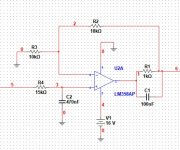
I used the following opamp circuit to convert to convert 0-5v to 0-16v. The circuit is done twice for volume and balance, A dual LM358 is utilized.
In addition, the default PWM frequency is very low on the arduino, I think it is around 960 hz. I tweaked some registers and cranked up the pwm frequency to 20khz.
In this implementation we will have 0-800 steps in the resolution of control. We only have arrow buttons for control. Supposedly there is a repeat code set when you press and hold an arrow button down. So I will probably have some special code to advance the step quickly when you hold an arrow button down and just bump it a single step when you tap the button for fine control.
The irremote library offers much functionality. It can work with a variety of remotes in addition to the cheapo remote that come with the IR module kit.
You can read more about it here https://www.makerguides.com/ir-receiver-remote-arduino-tutorial/
I have an old Radio Shack "Universal" IR remote. My hope is I can program it with my CD player codes as well and the Hafler codes and I can end up with a single remote to control both items.
We don't have a DAC on the Arduino. All we have is PWM output on an I/O pin. So - if we filter this PWM output we can a smoothed voltage that we can manipulate from 0-5 volts.
But 0-5 volts is insufficient for the Hafler. It wants 0-16 volts for volume and balance.
I used the following opamp circuit to convert to convert 0-5v to 0-16v. The circuit is done twice for volume and balance, A dual LM358 is utilized.
In addition, the default PWM frequency is very low on the arduino, I think it is around 960 hz. I tweaked some registers and cranked up the pwm frequency to 20khz.
In this implementation we will have 0-800 steps in the resolution of control. We only have arrow buttons for control. Supposedly there is a repeat code set when you press and hold an arrow button down. So I will probably have some special code to advance the step quickly when you hold an arrow button down and just bump it a single step when you tap the button for fine control.
The irremote library offers much functionality. It can work with a variety of remotes in addition to the cheapo remote that come with the IR module kit.
You can read more about it here https://www.makerguides.com/ir-receiver-remote-arduino-tutorial/
I have an old Radio Shack "Universal" IR remote. My hope is I can program it with my CD player codes as well and the Hafler codes and I can end up with a single remote to control both items.
Attachments
Last edited:
OK - After some more careful study of the IRIS schematic I now understand how the power up sequence is working.
The default state of the input selection MUX bus is "000" which selects the tuner.
MUTE is selected by the power supply crow bar circuit on power up. The crow bar circuit also tips the MUX latch which then locks in the tuner.
What is not clear is that somehow I am kicking the crow bar when I select AUX1,2 or Tape 1,2.
I can select PHONO, TUNER, CD, and VIDEO with no trouble. It is weird.
For the MUX and latch lines that go between the Arduino and the Hafler I am using the circuit below.
We have 10k pullups on the arduino I/O pins (left side of schematic) because we require a low state at the output of the the 7406's on powerup.
Again note the "isolation diode" that goes to the Hafler.. This circuit is repeated seven times Three for the MUX, One for the MUX latch, one for MUTE one for NORMAL and one for the Volume/Balance latch.
In "The CMOS Cookbook" Don Lancaster recommends the 7406 to interface TTL levels to higher CMOS levels.
I though that the 7406's would save space, but this turned out not to be the case. I think I would have been better off just using some 2n3904's configured as open collectors with 10k pullups instead.
I'll do that on the rev 2 board.
Attachments

Last edited:
Well, it seems that the reason I am having trouble switching to the AUX1,2 and Tape1,2 inputs is because these inputs all involve the MUX C line.
It seems that it is drawing too much current for this case and that is tripping the Hafler's power crowbar circuit. Which automatically sets mute and then delays a bit before defaulting back to TUNER.
I think what I will do is get rid of the 7406 drivers an instead just use 2n3904 for the MUX and select lines. Hopefully this will reduce current consumption all around. I don't want to overly tax the Hafler's +16v. In fact I might look into implementing some low power features on the Arduino.
On a lighter note - Volume, Balance, MUTE, UNMUTE are all functioning.
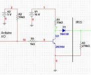
Converted over to 2n3904's to interface and now overall current consumption is now down to 60 ma. So my regulator now runs at body temperature..
Below shows how I'm doing it. The 270k resistor on the right resides on the IRIS and is present just for simulation purposes. This circuit is repeated for each of the seven control lines. Note that the default state is with the arduino i/o line pulled up to 5v. This means the transistors are turned on in the default state and the logic level is low behind the isolation diode.
Below shows how I'm doing it. The 270k resistor on the right resides on the IRIS and is present just for simulation purposes. This circuit is repeated for each of the seven control lines. Note that the default state is with the arduino i/o line pulled up to 5v. This means the transistors are turned on in the default state and the logic level is low behind the isolation diode.
Attachments
Despite the new changes I am still stumped as to why I cannot select the AUX and TAPE inputs..
In addition, I have discovered is that I cannot select AUX or TAPE inputs on the front panel of the IRIS with my remote board connected to the IRIS (in addition to the remote board not being able to select these inputs as well). The symptom is the associated input lights briefly and then the MUTE activates and then it selects TUNER. This is the normal power up sequence. It is as if a power supply glitch has occurred.
It is a mystery to me why this happens since all i/o lines that connect to the IRIS have the isolation diode and there is 0V potential behind the diode in the default state. In the idle state the IRIS should not even notice that the board is present.
The only commonality between these inputs is the "C" MUX line of the CD8051.
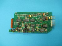
I was looking further at the photo of the IRIS original IR receiver board (attached below) and I notice two things that I have not implemented.
1) They have 22k resistors in series and before the diodes for the MUX lines.
2) They diode OR'd the MUX lines into the SELECT line. So if any MUX line goes High the select line goes High.
I will add the 22k resistors as an experiment.
But I don't believe the diode ORing is needed since I am activating this line correctly in software (not to mention I can select all other inputs correctly). In addition, I don't how this handles the case when TUNER is selected and and all MUX lines are low. If you look at the PCB you can see the select line is also routed elsewhere on the board so maybe this is how they handle that case.
The only thing I could think of is that since I am activating each I/O line separately in the code (and hence a tiny delay between each activation) that there is a fast race condition occurring somehow. In this case maybe the OR'ing with diodes may help. I guess I can try that.
In addition, I have discovered is that I cannot select AUX or TAPE inputs on the front panel of the IRIS with my remote board connected to the IRIS (in addition to the remote board not being able to select these inputs as well). The symptom is the associated input lights briefly and then the MUTE activates and then it selects TUNER. This is the normal power up sequence. It is as if a power supply glitch has occurred.
It is a mystery to me why this happens since all i/o lines that connect to the IRIS have the isolation diode and there is 0V potential behind the diode in the default state. In the idle state the IRIS should not even notice that the board is present.
The only commonality between these inputs is the "C" MUX line of the CD8051.
I was looking further at the photo of the IRIS original IR receiver board (attached below) and I notice two things that I have not implemented.
1) They have 22k resistors in series and before the diodes for the MUX lines.
2) They diode OR'd the MUX lines into the SELECT line. So if any MUX line goes High the select line goes High.
I will add the 22k resistors as an experiment.
But I don't believe the diode ORing is needed since I am activating this line correctly in software (not to mention I can select all other inputs correctly). In addition, I don't how this handles the case when TUNER is selected and and all MUX lines are low. If you look at the PCB you can see the select line is also routed elsewhere on the board so maybe this is how they handle that case.
The only thing I could think of is that since I am activating each I/O line separately in the code (and hence a tiny delay between each activation) that there is a fast race condition occurring somehow. In this case maybe the OR'ing with diodes may help. I guess I can try that.
Attachments
I really appreciate your efforts at keeping alive one of the greatest values in preamps ever made.
I think I found the problem... A while back I picked up a bunch of small signal diodes from an estate sale of a fellow Ham radio operator.
There was a box of a zillion small signal diodes. I assumed they were 1n4198s. Turns out most of them are Zener diodes!
Can you believe that? Right now I'm trying to figure out how many previous projects I used them on! I guess if the zener voltage was high enough those might be OK!
The worst part of it is that just a little while ago I ordered an assortment of zener diodes off of ebay!
I'll tell you something else... it is a pain in the neck to sort a pile of unsorted and various Zener diodes.
- Home
- Amplifiers
- Solid State
- Making a Hafler IRIS remote control