Beginner question for a schematic. I'd like to make a variable constant current sink so I can simply dial-in milliamp loads from 10mA to 100mA on the bench when testing power supplies for tube amps. I think in the industry they call this device an "active load" or something like that, anyway they are very expensive. In PSUD you can load your simulation with either a resistor or a CCS (in diagram below), that CCS (in yellow) is the thing I want to build for my bench. It should handle voltages from 90 to 450 volts and sink whatever current you select from 10mA to 200mA. I know I can simply use big resistors on the bench, but to land at the load you want you have to have that resistor on hand for the voltage you are targeting, then you have to do ohms law with all your spare big resistors you do have to get close to the mA you want. So I thought there must be a way to simply build a current sink where I can dial in (or rotary switch) to the amount of current I want to draw from the power supply under test. Can I simply do this with a MOSFET and a 500 ohm rheostat wired source to gate to self bias the FET as a CCS? Then make a paper vernier dial of the currents I can dial into, put it in a box and done. Or is this a bigger project? Has anyone built such a device here that will cover the voltages and amount of constant current I want to present to the PS DUT? Thx.

you can make a constant current sink out of a LM317HV and two EL34 tubes.
Using mosfets is possible aswell, but try to use linear specified mosfets.
Using mosfets is possible aswell, but try to use linear specified mosfets.
A high-voltage MOSFET and an opamp can be cobbled together to become a constant current source (CCS). Stability can be a challenge with such a circuit, but it is a possibility.
Do keep in mind that 200 mA at tube voltages is quite a bit of power, so the CCS needs a heat sink in order to survive. Or it needs to be based on a vacuum tube that can handle the dissipated power as suggested above.
Tom
Do keep in mind that 200 mA at tube voltages is quite a bit of power, so the CCS needs a heat sink in order to survive. Or it needs to be based on a vacuum tube that can handle the dissipated power as suggested above.
Tom

Thanks Tom and v4lvelover, in time I will attempt to put together a schematic based on a large MOSFET that is specified as useful for active load designs, I came across a few candidates of high voltage, high current, high on resistance MOSFETS. My attempt will have errors I'm sure but a start. I don't suspect that Ill need 200ma after all, but I'd like to be able to simply dial a PS under test to 100 ma starting at 10 ma. I think it would be a useful device to determine a transformer that is neither undersized or too far oversized (for chassis size considerations). As well as to see how well it regulates and how well it kills ripple, how hot it gets, etc. I would imagine it should have its own ma meter and sense resistor too.
I'm thinking this MOSFET might be good 1000V; 6A; 2.2 ohm on resistance; 300W. In the TO247 version, very big heatsink.
https://www.mouser.com/datasheet/2/240/media-3322848.pdf
https://www.mouser.com/datasheet/2/240/media-3322848.pdf
You can buy active loads on Aliexpress though the maximum load voltage is unlikely to be your required 450V. But it gives you a mechanical template to build on. This one for example maxes out at 150V :
https://www.aliexpress.com/item/1005005495497498.html
The use of a PC CPU cooler is a very low-cost option for the heatsink.
https://www.aliexpress.com/item/1005005495497498.html
The use of a PC CPU cooler is a very low-cost option for the heatsink.
I'm thinking this MOSFET might be good 1000V; 6A; 2.2 ohm on resistance; 300W. In the TO247 version, very big heatsink.
https://www.mouser.com/datasheet/2/240/media-3322848.pdf
The safe operating area looks good and it is meant for analogue applications (I mean applications other than switching). As it is a depletion device, your idea of just adding a rheostat and a big heatsink should work. It's probably wise to add a fixed resistor or a rheostat you can't easily access in series to ensure you don't accidentally turn up the current to the full IDSS of at least 6 A.
One possibility is a stock constant current sink circuit (opamp + NPN BJT) with a cascoded device to provide the high voltage high power capability. I suspect it gets tricky if you want a good bandwidth - finding a cascode device with low output capacitance would be important for this - 45W is a big ask though.
Power supplies usually have big capacitors across their outputs, so I doubt you need a large bandwidth for Windcrest77's application.
The safe operating area looks good and it is meant for analogue applications (I mean applications other than switching). As it is a depletion device, your idea of just adding a rheostat and a big heatsink should work. It's probably wise to add a fixed resistor or a rheostat you can't easily access in series to ensure you don't accidentally turn up the current to the full IDSS of at least 6 A.
Thanks, as a first go I'll try that simple method, very few parts, I can get the grid stopper very close to the pin. I like the form factor abraxalito pointed at. Basically a cube with a fan, the rheostat, the 1 ohm sense resistor, and an old analog mv meter could round it out. I will sandwich the rheostat with a series resistor that stops the CW side of the rheostat at probably 100ma. Or maybe a switch and two resistors for the occasional time I want 150ma.
Some use a ferrite bead on the gate and another on the source. Also, test at a reasonably low voltage first.
Tom
Tom
Oh... And protect your test equipment. I'm thinking here of, say, a signal generator that could be used to modulate or control the CCS current. You really don't want to destroy your test equipment just because the MOSFET in the CCS decides to turn to slag.
If you're just using the CCS for prototyping and such, I'd have a look at a CPU cooler. They're designed to remove quite a bit of power (100+ W in some cases).
Tom
If you're just using the CCS for prototyping and such, I'd have a look at a CPU cooler. They're designed to remove quite a bit of power (100+ W in some cases).
Tom
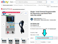
It appears you can buy the complete unit, designed and assembled and tested, including fans and digital panel meters, from eBay. I bought a similar unit years ago, for solid state PSU testing (@ lower voltages!), and really like the device.
Beware, the specs are not misleading but they are perhaps confusing. The model below has these absolute maximum ratings:
If you run it with Iin = 14.99 amperes, Vin must be less than 26.6 volts
_
Beware, the specs are not misleading but they are perhaps confusing. The model below has these absolute maximum ratings:
- Vin < 500 volts . . . . and also
- Iin < 15 amperes . . . . and also
- Power = (Vin * Iin) < 400 watts
If you run it with Iin = 14.99 amperes, Vin must be less than 26.6 volts
_
Attachments
Wow, thanks, all the ones I saw commercially were $2000 range. This would fit the bill and save my time. AliExpress has several models, search for "dc electronic load" and there is a model that goes to 500V.
Last edited:
Would something like this work? Just a quick proof of concept. Battery powered, voltage and current limits determined by FET choice. Voltage on opamp input sets current limit so could be a pot fed from a micropower reference from the 9 volt battery (if accuracy needed) or otherwise just a suitable pot padded with a resistor to limit the range.

Voltage in Green and Current in red (right hand scale)

Voltage in Green and Current in red (right hand scale)
On Aliexpress the ET5411A model appears to be rated to 500V for tube amp supply testing, if anyone is interested, and it does more than just CC loading. This thing is being sold my hundreds of shops so it's probably pretty mature.
https://ae01.alicdn.com/kf/S746b84c3edb442ab8d81e062e2c57e29u.jpg
https://ae01.alicdn.com/kf/S746b84c3edb442ab8d81e062e2c57e29u.jpg
On Aliexpress the ET5411A model appears to be rated to 500V
very similar, extremely similar to the one in post #14 of this thread
_
Attachments

- Home
- Amplifiers
- Power Supplies
- Making a bench variable constant current sink?