Hello, I've been building speakers for a while now, I've learnt a lot of things and tips.
The only thing I still can't figure out is how to make angled speakers live this design that I've made in Sketchup.
Any suggestions?
The only thing I still can't figure out is how to make angled speakers live this design that I've made in Sketchup.
Any suggestions?
You bored or drinking again?😛
I'd appreciate serious help.
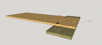
Jeremy - does that low resolution graphic on the left suggest that stacked lamination is intended?
If so, and if you need to ask how to go about cutting and building such a project, you might want to consider a more conventional flat sheet goods fabrication to start with?
There's more than several methods / techniques with which to fabricate parts for such a tilted enclosure - I've done that at least half a dozen times.
Jeremy - does that low resolution graphic on the left suggest that stacked lamination is intended?
If so, and if you need to ask how to go about cutting and building such a project, you might want to consider a more conventional flat sheet goods fabrication to start with?
There's more than several methods / techniques with which to fabricate parts for such a tilted enclosure - I've done that at least half a dozen times.
And that's why I asked, it would be very useful if you could explain or give a link.
I would like to build speakers like that but I don't understand how it works...
Sanding a piece until it's done maybe?
Let's repeat the question again - which of the two methods are you considering
- stacked lamination
or
- conventional flat panel?
There are at least a couple of very detailed threads on the former - check out probably the most comprehensive one, which includes not only physical construction, but also the design process of the total system.
http://www.diyaudio.com/forums/full...o-towers-25-driver-full-range-line-array.html
To clarify, for several reasons, including my laziness, the several titled enclosures I've built have all been with conventional flat sheet goods.
With that method, it's really as simple as just cutting the appropriate angles - of which there are several ways to go about. A sliding table saw is bloody handy to have access to for the side panels, but a straight edge and skil-saw or router can achieve the same results. As for the matching bevels on the narrower lateral pieces -including braces if used, table saw and miter gauge makes pretty quick work of those.
-
Last edited:
Let's repeat the question again - which of the two methods are you considering
- stacked lamination
or
- conventional flat panel?
There are at least a couple of very detailed threads on the former - check out probably the most comprehensive one, which includes not only physical construction, but also the design process of the total system.
http://www.diyaudio.com/forums/full...o-towers-25-driver-full-range-line-array.html
To clarify, for several reasons, including my laziness, the several titled enclosures I've built have all been with conventional flat sheet goods.
With that method, it's really as simple as just cutting the appropriate angles - of which there are several ways to go about. A sliding table saw is bloody handy to have access to for the side panels, but a straight edge and skil-saw or router can achieve the same results. As for the matching bevels on the narrower lateral pieces -including braces if used, table saw and miter gauge makes pretty quick work of those.
-
Sorry I didn't get the first answer.
I would like to build with conventional MDF panels.
While I'd counsel strongly against MDF for speakers, fabrication and assembly with either type of material is really pretty straightforward.
What type of tools / saws do you have access to? The precision of clean square edges on sides, and the numerous angled cuts on pieces forming the lateral exterior shell is important for structural integrity, and I'd definitely not want to rely on the "gap-filling" ability of expanding moisture cured polyurethane glues ( Gorilla, etc), as is sometimes seen written about. As far as I'm concerned, the joint should be as close to air-tight as possible before glue and any mechanical fasteners such as nails / screws.
I personally use combinations of dadoes and cleats on larger designs to achieve more glue surface area at joints, but on smaller boxes, simple butt joints are quite adequate with today's cabinet glues.
I assume you know how to design the slanted parts to get the dimensions, angle, etc, and you're asking how to cut them:
I do it with a contractor size table saw. I install a straight 24" strip of plywood on the miter gage to make it longer so it can support long panel of wood without rocking the angle during cut. I use an architect's drawing protractor to accurate set the miter gage angle to the miter gage slot in the table. (The angle to the blade is irrelevant.) There are many table saw protractor rulers available. I like the architect/drafting type because it is very accurate and large, can set miter gage angle directly against it.
Cut the side panels to net width, with width dimension normal (perpendicular) to the edges. To make the top and bottom cuts of the side panels: The blade is set to 90 degrees perpendicular to the table. I use a digital blade angle gage to set this to 0.1 degrees tolerance, because the angle gage on the saw is not accurate enough for our purposes. Set the miter gage angle with protractor. Place the workpiece on the table and hold it tightly against the wood miter gage with fingers. The workpiece should be well supported and stable during the cut. It is hard to hold it down to the table and hold it tight against the miter at the same time. If you have a small tablesaw rig a side table to hold up the long end. Make the cut. Cry and swear because you messed it up. Improve your setup and try again until you get it right.
Baffle: Cut width with 90 blade angle, using saw fence. Set miter gage to 90 degrees to slot. I use a 12" carpenters triangle for this. Set blade angle to your desired tilt angle using blade angle gage. Cut top of baffle, then bottom to length as before. You may be able to use fence for the top and bottom cuts if your tablesaw skill is good and baffle not too narrow. Repeat same procedure for the rear panel and the top and bottom panels.
The easiest way to do this is if the side panels are large enough to cover the inner parts. Then glue all the inner parts to one side of the side panel, square. Then add bracing, and add on the top side panel. This way you can rip all the top, bottom, front baffle and read panel, and inner brace pieces to the same width at hte same time, then just cut them to length with the same blade angle using fence or miter gage. With this method, you can cut the side panels to be 1/4" to wide in both dimensions, so you can leave a 1/8" overhang when the inner pieces are glued on. Then you can use a flush trim router bit to trim the side panels flush to the inner pieces after glue dries. This minimizes sanding.
I have all the necessary tools like the table saw, routers, trimmers.
I already build and sell speakers, but I failed every time I tried this design
I already build and sell speakers, but I failed every time I tried this design
Well, it's really not rocket science - otherwise my own builds would have failed catastrophically. The key is accurate shop drawings - I've been using a 20+yr old Autosketch program that works like a charm, including measuring bevel angles.
Rich pretty much covered the cutting process above
Those cheap magnetic gauges are a godsend for getting angles exactly right on the table saw
Rich pretty much covered the cutting process above
Those cheap magnetic gauges are a godsend for getting angles exactly right on the table saw
An externally hosted image should be here but it was not working when we last tested it.
Well, it's really not rocket science - otherwise my own builds would have failed catastrophically. The key is accurate shop drawings - I've been using a 20+yr old Autosketch program that works like a charm, including measuring bevel angles.
well as a user of a badly out of date version of autosketch for 15 years, I can recommend giving sketchup a go, if you have already and decided it's too weird then I'd say try again, the speed is something else, and it's just as accurate.
*It's funny how Autosketch become such a bog in later versions from such a useful program, that even autocad decided that they couldn't fix it and just gave up.
I've always used and still using Sketchup Pro.
So I'm good on that part
For the flat edge side panles with a front to back slope, I've done many cuts of this sort with a trimmer bit and router. Make a line on the panel where the cut is going and use a Jig Saw to cut the piece off but leave about 2mm extra beyond the line. Then Line up a flat guide board on the line and clamp it to panel. Let the edge trimmer bit bearing ride the guide board. Perfect Cut! You could use top or bottom bearing bit, just clamp guide board to top or bottom for appropriate bit.
I have base plates with adjustable feet to angle speakers.
Google Sketchup is a charm and always make a drawing before I start.
I have base plates with adjustable feet to angle speakers.
Google Sketchup is a charm and always make a drawing before I start.
Last edited:
Joel - a couple of pictures of that jig & process would be very illuminating
I hope this drawing describes it well. After one side panel is trimmed, it can be used for an accurate template for remaining 3.
Another way is to build this box is with extra length on side panels. Cut bottom board with appropriate angle on front and back edge. accurately assemble box with perfect placement of the bottom board, with bottom board as a guide flush trim off the extra length on side panels.
Curious what the Orig Poster has in mind for complete method of construction? Also Painted or veneered can create a slightly different method.
Lately, I'm thinking I want the bottom to protrude from the sides, front and back so painted edge wont scrape on floor. ideas for floor speakers only.
For bookshelf speakers I like the bottom to be finished same as sides and top.
Attachments
On the path to success, mistakes are required, but failure is optional. 😀
First decide you can do it - you've learned much harder things than this in your life. Then practice building a bunch of small boxes, full of mistakes! Then you can analyze the flaws and ask questions to understand the causes. Soon there's no more mistakes.
This is the blade angle gage I use, it's good. But don't leave the battery in it for storage or it will drain.
Jeremy - if you have a decent table saw and sliding mitre gauge, or can build a sled, the repeated angled cuts required on the lateral pieces for something like this is a piece of cake.
I usually revised the joint overlaps from Dave's original drawings so the tops and bottoms are inset. In this case, the tapered TL for the Fostex driver means the top runs slightly deeper.
As Joel notes, assembly methods can be affected by finishing choices. I've always found veneering to take far less time - and often less money - than any paint job I'd want to live with. And I just prefer the look of wood - so brad nails and even screws filled with bondo are just fine - a good R/O sanding and you're good to go.
Just note that depending on overall dimensions, tilt, and number / weight and locations of drivers, a tilted enclosure can get tippy - so extended base plate, or outriggers can't hurt.
Attachments
bevel gauge when making angled speaker unit
If your making angled speakers, a drawing can only get you so far, you need to make sure you use a bevel gauge so your application will fit as close to the plan as possible.
If your making angled speakers, a drawing can only get you so far, you need to make sure you use a bevel gauge so your application will fit as close to the plan as possible.
- Home
- Design & Build
- Construction Tips
- Make an angled speaker