When winding a mains transformer with center tapped secondary the outer half winding will be larger than the inner half.
Also the wire resistance will be greater than the inner winding.
How much will this affect the voltage?
Also the wire resistance will be greater than the inner winding.
How much will this affect the voltage?

The NO LOAD voltage will not be affected, but resistance is resistance and there will be a resistance in series with the outer leg that will not be equal to the inner leg. This will affect the LOADED output voltage depending on the load VS the wire size.
There are three ways to deal with this. Ignore it which is common unless the wire gauge is small and there are lots of turns. Add a resistor in series with the leg having the lowest DCR so that both legs measure the same with an ohmmeter. Wind the outer layer with a slightly thicker wire gauge. This is commonly done in OPT's where it makes more of a difference.
There are three ways to deal with this. Ignore it which is common unless the wire gauge is small and there are lots of turns. Add a resistor in series with the leg having the lowest DCR so that both legs measure the same with an ohmmeter. Wind the outer layer with a slightly thicker wire gauge. This is commonly done in OPT's where it makes more of a difference.
There might be a pinch more of voltage loss in the outer winding side of the center-tap when conducting appreciable current do to the added DCR of the longer outer turns in the coil. It would be minimal though. Easy way to find out about this in your transformer is to measure the DCR of the two halves of the winding and compare. Then see if any difference is significant to you based on your current draw.It won't, voltage depends on the turns count, which determines the flux linkage with the coil. Assuming a ferromagnetic core transformer, which all mains transformers are.
Hi
It' s an over way and better for me.
see : Lee_1955_Electronic_Transformers_and_Circuits
In this way there is no need to electrostatric screem

see
It' s an over way and better for me.
see : Lee_1955_Electronic_Transformers_and_Circuits
In this way there is no need to electrostatric screem
see
Current draw won't be all that much since the transformer will be used for a very low powered SET amp . . . 25 mA.Then see if any difference is significant to you based on your current draw.
It's possible that a transformer be wound that way, but likely the two winding will be wound together, and the "center tap" is actually opposite ends of different windings. This also applies to dual primaries for 120/240VAC. In any case, a transformer should never be loaded so heavily that it makes any difference.
i moved on from center tapped ptx a long time ago, why? because i make my own....
full wave w/o center taps is best imho, transformer utilization is 30% better,
this means lower voltage involved, imagine, a pa06 with 360-0-360vac, that is 720vac of high voltage,
i make my own with single 330vac winding, very convenient to make, faster to wind and using thicker wire, and cheaper too....what is n0t to like?,
full wave voltage doubler is even better, at half the turns in the full wave case....
the Harman Kardon Citation 2, the Marantz 9, and many other Japanese tube amps did this even during the late 70's to name a few...
Agreed, all my transformers are full wave no CT, for optimal transformer utilization.
Also makes snubbing a no-brainer, just a single RC, and no debate about whether one should snub to the CT or not (you don't need to, but there will always be the DIY debate).
How to twist the wires is obvious, no question about the 3rd wire. Where to ground the circuit common, etc.
Doublers I have not pursued; I guess if you have the room for capacitance and don't mind the peak currents, they are great from a transformer winding standpoint. But I optimize my filter designs around Small C, Large L, Large C, such that my transformer current is reasonably sinusoidal, rather than having a high crest factor.
Depends on your goals I guess.
Attachments
filter caps have grown in capacity and are now a lot smaller....
today, I am exited to use the cbb65 polypropylene caps that are huge capacity and reasonable volumes..
http://www.capacitorc.com/uploads/CBB65.pdf
today, I am exited to use the cbb65 polypropylene caps that are huge capacity and reasonable volumes..
http://www.capacitorc.com/uploads/CBB65.pdf
yes, since i amp fond of using tv tubes, a full wave doubler makes it convenient to supply G2 with much lower voltages rather than dropping the voltage from a high B+,Depends on your goals I guess.
A bridge can also supply 1/2 voltage if the transformer is center-tapped. Doubler and bridge are very near to identical if corresponding transformers are used (doubler transformer has twice the copper cross-section, half the length, 0.25 times the resistance). Two diode drops in either, but is a greater proportion at half the voltage. Capacitors will carry 60 Hz ripple current in a doubler, and electrolytics have slightly higher ESR at 60 Hz than 120. But output ripple, regulation, primary current / waveform are the same. Center-tap full-wave needs 40% more VA rating in the secondary (and of course transformer size increases) for the same DC output.
Of only historic interest to me - as the heaters of a directly-heated rectifier are typically in series, one side will have a peak about 2.5V higher - which half depends on relative polarity of the rectifier winding. The higher side should be used with the the outside secondary half with higher resistance. This will minimize the 60 Hz ripple component caused by this imbalance. Can't do that with indirectly heated rectifiers.
i doubt it will be 60 hz ripple in a full wave voltage doubler, in a half wave doubler yes, but i never used those....A bridge can also supply 1/2 voltage if the transformer is center-tapped. Doubler and bridge are very near to identical if corresponding transformers are used (doubler transformer has twice the copper cross-section, half the length, 0.25 times the resistance). Two diode drops in either, but is a greater proportion at half the voltage. Capacitors will carry 60 Hz ripple current in a doubler, and electrolytics have slightly higher ESR at 60 Hz than 120. But output ripple, regulation, primary current / waveform are the same. Center-tap full-wave needs 40% more VA rating in the secondary (and of course transformer size increases) for the same DC output.
i like to overbuild by ptx traffos....and keep them cool...
Hi
In a full wave doubler, you could connect the side secondary (generally the inter) in interface with the primary, to between condos.
This pt is relatively fixed by them and degease hum
Yan
In a full wave doubler, you could connect the side secondary (generally the inter) in interface with the primary, to between condos.
This pt is relatively fixed by them and degease hum
Yan
The output ripple is 120 Hz. Each of the capacitors in the doubler carries 60 Hz ripple current. They're in series; the composite waveform is 120 Hz,i doubt it will be 60 hz ripple in a full wave voltage doubler, in a half wave doubler yes, but i never used those....
i like to overbuild by ptx traffos....and keep them cool...
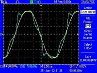
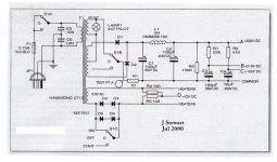
Here is another Trick PS I used in an experimental 6LU8 SET or SEUL Amp from year 2000.
Simply adjusted to the best condition as seen by the PS current pulses developed across a 10R
resister in the return lead to the HV CT. There is also a quad of back to back silicon diodes
to provide a reduced voltage standby mode for the tube heaters.
And a 6BQ7 FB Pair to get some gain.
Published in the Glass Audio Projects Book, July 2002. And all in a dressed up PDF.👍
Attachments
- Home
- Amplifiers
- Tubes / Valves
- Mains transformer-center tapped secondary question