Hi,
Actually, YES, regulators produce noise, as do resistors and whatever else.
A regulator is in the end a series pass or shunt element combined with an error amplifier and a reference. The error amplifier will have a certain amount of self noise as will the reference.
The LM1083(84/85/86) is rated to have it's output noise (10Hz-10KHz, RMS measurements) as a percentage of the Output Voltage, namely 0.003%.
This in case of Vout = Vref comes to 0.003% of 1.25V or 37.5uV RMS (and likely a considerable "spikey" peak amount).
The TL431 is shown with an RMS equivalent input noise on a 2.5V Reference with peaks around 5uV and an estimated (eyeballed) RMS Vallue of maybe 2uV, which shows the TL431 as about 26db better on self noise.
Now the OUTPUT NOISE after regulation is another story.
This comes as a combination of the self noise (usually the smallest part in AC line operated gear) and a percentage of the the noise present on the input of the regulator. The term "ripple rejection" refers to the amount by which the noise on the input of a regulator is rejected.
The LT1083 has 75db ripple rejection @ 100Hz and of 25db @ 100KHz, meaning the rejection of input ripple & noise falls with appx. a 1st order slope (20db/decade).
Now the TL431 has no ripple rejection in the conventional sense. Being a shunt element it's dynamic impedance forms a voltage divider with the series element. The dynamic impedance of the TL431 is around 0.15 Ohm if the Anode/Reference connection is capcitively bypassed, the impedance remaining flat up to around 60KHz and reaching 0.2 Ohm @ 100KHz and then rising to 10R @ 1MHz where the impedance levels out.
If we now utilise a suitable set of bypass capacitors with an ESR of around 0.15R and a suitable capacitance value to give a low impedance around the 100KHz region (say Xc around 0.05R @ 100Khz which means a 22uF Cap with ESR = 0.15R or with Z @ 100Khz = 0.25R) and to continue this impedance into the high MHz range we will have an almost constant PSU node impedance of 0.15 Ohm from DC to many MHz.
If we now choose an apropriate series element (say a 100R Resistor) we can determine the ripple rejection as a direct result of the Voltage divider formed by the series element and the Shunt as 100.15/0.15=668=56db from DC to many MHz.
This illustrates that the reippel rejection ration is a direct function of the Impedance of the series element. If we (for arguments sake) used a LM334 current source as series element with 10mA current we would have a dynamic impedance of around 10^6 Ohm or 1MOhm dynamic impedance up to 10KHz and then falling by a factor 10 per octave. So up to 10KHz our ripple rejection would become around 1000000.15/0.15=6666668=136db with a fall of around 20db/Octave above 10KHz.
By using a cascode (J-Fet) around the CCS we can keep the Impedance up to much higher frequencies so using suitable RF layout and design technicques a few components can be combined to form a simple local regulator that will reject any source ripple by >> 100db and will have a few uV self noise. Of course, it helps to understand what one does to get good results from the TL431, but that is simply the "usual" thing anyway.
I have not touched at all on the load transient "dynamic" impedance, a very interesting subject BTW with respect to sonics. The transient of the usual Op-Amp Regs (be they LM317 or Jung/Sulzer Types) is pretty poor, measuring the dynamic impedance of the Reg with a squarewave pulsed load shows very interesting happenings indicating ringing and loads of overswing which usually gets worse with capacitive output bypassing, sometimes much worse.
The TL431 Shunt by comparison is in effect "non reactive" even when bypassed and shows a very nice behaviour.
So, I hope that gives some ideas about what regulators do and how/why they do what they do. I'd be interested to know how Andy managed to show a -75db "selfnoise" trace for the TL431 when it should be around -114db, but that as they say is another story.
Sayonara
dddac said:
PS: I dont "think" regulators are producing noise themselves when fed by a battery.... but may be I am wrong (I don't have universal wishdom after all) ---> can any one react on this with some proof (no opinions please ...)
Actually, YES, regulators produce noise, as do resistors and whatever else.
A regulator is in the end a series pass or shunt element combined with an error amplifier and a reference. The error amplifier will have a certain amount of self noise as will the reference.
The LM1083(84/85/86) is rated to have it's output noise (10Hz-10KHz, RMS measurements) as a percentage of the Output Voltage, namely 0.003%.
This in case of Vout = Vref comes to 0.003% of 1.25V or 37.5uV RMS (and likely a considerable "spikey" peak amount).
The TL431 is shown with an RMS equivalent input noise on a 2.5V Reference with peaks around 5uV and an estimated (eyeballed) RMS Vallue of maybe 2uV, which shows the TL431 as about 26db better on self noise.
Now the OUTPUT NOISE after regulation is another story.
This comes as a combination of the self noise (usually the smallest part in AC line operated gear) and a percentage of the the noise present on the input of the regulator. The term "ripple rejection" refers to the amount by which the noise on the input of a regulator is rejected.
The LT1083 has 75db ripple rejection @ 100Hz and of 25db @ 100KHz, meaning the rejection of input ripple & noise falls with appx. a 1st order slope (20db/decade).
Now the TL431 has no ripple rejection in the conventional sense. Being a shunt element it's dynamic impedance forms a voltage divider with the series element. The dynamic impedance of the TL431 is around 0.15 Ohm if the Anode/Reference connection is capcitively bypassed, the impedance remaining flat up to around 60KHz and reaching 0.2 Ohm @ 100KHz and then rising to 10R @ 1MHz where the impedance levels out.
If we now utilise a suitable set of bypass capacitors with an ESR of around 0.15R and a suitable capacitance value to give a low impedance around the 100KHz region (say Xc around 0.05R @ 100Khz which means a 22uF Cap with ESR = 0.15R or with Z @ 100Khz = 0.25R) and to continue this impedance into the high MHz range we will have an almost constant PSU node impedance of 0.15 Ohm from DC to many MHz.
If we now choose an apropriate series element (say a 100R Resistor) we can determine the ripple rejection as a direct result of the Voltage divider formed by the series element and the Shunt as 100.15/0.15=668=56db from DC to many MHz.
This illustrates that the reippel rejection ration is a direct function of the Impedance of the series element. If we (for arguments sake) used a LM334 current source as series element with 10mA current we would have a dynamic impedance of around 10^6 Ohm or 1MOhm dynamic impedance up to 10KHz and then falling by a factor 10 per octave. So up to 10KHz our ripple rejection would become around 1000000.15/0.15=6666668=136db with a fall of around 20db/Octave above 10KHz.
By using a cascode (J-Fet) around the CCS we can keep the Impedance up to much higher frequencies so using suitable RF layout and design technicques a few components can be combined to form a simple local regulator that will reject any source ripple by >> 100db and will have a few uV self noise. Of course, it helps to understand what one does to get good results from the TL431, but that is simply the "usual" thing anyway.
I have not touched at all on the load transient "dynamic" impedance, a very interesting subject BTW with respect to sonics. The transient of the usual Op-Amp Regs (be they LM317 or Jung/Sulzer Types) is pretty poor, measuring the dynamic impedance of the Reg with a squarewave pulsed load shows very interesting happenings indicating ringing and loads of overswing which usually gets worse with capacitive output bypassing, sometimes much worse.
The TL431 Shunt by comparison is in effect "non reactive" even when bypassed and shows a very nice behaviour.
So, I hope that gives some ideas about what regulators do and how/why they do what they do. I'd be interested to know how Andy managed to show a -75db "selfnoise" trace for the TL431 when it should be around -114db, but that as they say is another story.
Sayonara
One does wonder what our friend Andy had to do to get such a noisespectrum from a TL431. It must have taken either a faulty exemplar or much work (or much incompetence?) to get those kind of results.
The first point is those traces are relative, and not calibrated in any absolute sense.
The relative measurements are valid though. They were comparisons of various reg's running at *24V*, one has to bear in mind the noise of the TL431 is shown at the reference voltage and is amplified by the noise gain of the subsequent error amp. Run it at high Vout and the noise is a lot worse than the headline figure would have you believe.
Also the LT108x series, without exception in my experience, perform better than the spec sheet value of 0.003% of Vout. If this were not the case they would measure the same as the LM317' s, but they don't being a significant amount quieter in all cases.
I have since realised it's possible to bypass the divider to reduce the noise gain, but either way, I personally didn't like the results obtained, compared to other approaches.
It serves to usefully illustrate though that unless one is clear about the exact implementation (and I readily accept I didn't show any in that post) the discussions are somewhat pointless.
The same holds true for your comments about transient loading of linear reg's, of any topology. It's not difficult to acheive extremely high levels of performance here, but as with all areas of audio electronics endeavour, one MUST consider each application to be specific to a given set of circumstances and ideally optimise for that, there's few universal truths here.
Andy.
The TL431 has higher output impedance than any modern 3 pin series regulator. That 0.2 Ohm is the best case (edit: unity gain - 2.5V, any higher voltage and it will go higher). This will be directly related to its poorer ability to shunt the currents at its output. The situation at higher frequencies might be still discussed, but inside the audio band, with TL431 you’ll hardly reach that low impedance you could have with (still cheap) series regulators, whose output impedance is here often between 0.01 and 0.1 Ohm (and can go as low as 0.001 Ohm). So, Andy’s results, which apply exactly to this range, are not strange to me. (This, of course, doesn’t mean that he did not screw up something. 😉 )
Pedja
PS: The output impedance is only a part of the story though.
Pedja
PS: The output impedance is only a part of the story though.
Bottom line for us hobby'ist is that for Doede's DAC... the TL431 "scare" ;-) does not apply to us IF using the batteries since the self noise of a TL431 is very low...
And since the TL431 HAS a 20uF cap following it...it is also quiet? in the scope of this thread "Mains PS for DDDAC"??????
Cheers,
Bas
And since the TL431 HAS a 20uF cap following it...it is also quiet? in the scope of this thread "Mains PS for DDDAC"??????
Cheers,
Bas
Andy,
The fact it was 24V might be the answer. The TL431 will perform better at lower voltages.
Pedja
The fact it was 24V might be the answer. The TL431 will perform better at lower voltages.
Pedja
Konnichiwa,
Funny that the LM317/LT1086 traces are pretty much where I'd expect them....
Which illustrates merely that you do not know how to apply the TL431, if applied correctly the noise gain is unity and only the DC (and VERY LOW AC) gain is higher than that.
Fine. However, shall we agree that the measurements shown for the TL431 are NOT representative of a correctly implemented unit?
Actually, the same as discussed above with Andy Applies. You must bypass the Voltage divider for AC.
While I note that at near DC frequencies cheap series regs have a very low Output Impedance, the same is not neccesarily the case at higher frequencies (especially not in the region where digital noise falls), moreover, I have seen many series regs behaving "funny" when faced with transients, including behaviour that shows a very substantial NEGATIVE dynamic output impedance on falling current edges.
The point is that practically all series regs do not tolerate "spikey noise" very well, be it on the input or output. And it is of course exactly such noise which is created by CMOS logic switching (for example).
While it is possible (and easy) to get a lower PSU Node impedance at lower frequencies than the TL431 does it is near impossible to match the consistency of the PSU impedance over frequency that the correctly bypassed and applied TL431 offers.
Of course, if all you are after is bare specmanship to show impressive numbers the TL431 is the wrong choice... ;-)
Sayonara
ALW said:
The first point is those traces are relative, and not calibrated in any absolute sense.
Funny that the LM317/LT1086 traces are pretty much where I'd expect them....
ALW said:
The relative measurements are valid though. They were comparisons of various reg's running at *24V*, one has to bear in mind the noise of the TL431 is shown at the reference voltage and is amplified by the noise gain of the subsequent error amp. Run it at high Vout and the noise is a lot worse than the headline figure would have you believe.
Which illustrates merely that you do not know how to apply the TL431, if applied correctly the noise gain is unity and only the DC (and VERY LOW AC) gain is higher than that.
ALW said:
I have since realised it's possible to bypass the divider to reduce the noise gain, but either way, I personally didn't like the results obtained, compared to other approaches.
Fine. However, shall we agree that the measurements shown for the TL431 are NOT representative of a correctly implemented unit?
Pedja said:The TL431 has higher output impedance than any modern 3 pin series regulator. That 0.2 Ohm is the best case (5V, any higher voltage and it will go higher).
Actually, the same as discussed above with Andy Applies. You must bypass the Voltage divider for AC.
Pedja said:This will be directly related to its poorer ability to shunt the currents at its output. The situation at higher frequencies might be still discussed, but inside the audio band, with TL431 you’ll hardly reach that low impedance you could have with (still cheap) series regulators, whose output impedance is here often between 0.01 and 0.1 Ohm (and can go as low as 0.001 Ohm).
While I note that at near DC frequencies cheap series regs have a very low Output Impedance, the same is not neccesarily the case at higher frequencies (especially not in the region where digital noise falls), moreover, I have seen many series regs behaving "funny" when faced with transients, including behaviour that shows a very substantial NEGATIVE dynamic output impedance on falling current edges.
The point is that practically all series regs do not tolerate "spikey noise" very well, be it on the input or output. And it is of course exactly such noise which is created by CMOS logic switching (for example).
While it is possible (and easy) to get a lower PSU Node impedance at lower frequencies than the TL431 does it is near impossible to match the consistency of the PSU impedance over frequency that the correctly bypassed and applied TL431 offers.
Of course, if all you are after is bare specmanship to show impressive numbers the TL431 is the wrong choice... ;-)
Sayonara
Kuei Yang Wang said:You must bypass the Voltage divider for AC.
Yes, that will work.
There can be made a shunt regulator with better specs. However, one such regulator with huge bandwidth (MHz) of the relatively low (below 0.2 Ohm) output impedance that I tried (in the analog supply for the TDA1541A chip) in the previous weeks was sonically inferior to the TL431.Of course, if all you are after is bare specmanship to show impressive numbers the TL431 is the wrong choice... ;-)
Pedja
Powersupply for TDA1543
Hi,
Enough theorizing!
I would suggest to to build my triple Darlington supply with the LM329 , possibly upped up a few volts with 1N4848's if you like +8V supply, and compare the sound with battery supply (lead acid gel packs) IN YOUR SYSTEM.😱
Hi,
Enough theorizing!
I would suggest to to build my triple Darlington supply with the LM329 , possibly upped up a few volts with 1N4848's if you like +8V supply, and compare the sound with battery supply (lead acid gel packs) IN YOUR SYSTEM.😱
Which illustrates merely that you do not know how to apply the TL431, if applied correctly the noise gain is unity and only the DC (and VERY LOW AC) gain is higher than that.
Fine. However, shall we agree that the measurements shown for the TL431 are NOT representative of a correctly implemented unit?
I only disagree over the words 'correctly implemented'.
Both sets of IC's were implemented *exactly* as per the datasheet recommendations, which is how 99% of users would implement them. Under those conditions the noise performance of the 431 is a lot worse.
The datasheets for most manufacturers I've looked at do not mention reducing the noise gain of the 431 as an option and of course the effect of doing that does not affect the noise gain of the circuit in isolation, other parameters are affected.
The other thing one has to bear in mind is the 431 is far less graceful than assumed here by some, as is demonstrated by the unusually clearly presented cap load plots in the datasheets.
Change the noise gain of the circuit and these become invalid, leaving the end user to do the work for him/herself, in terms of determining stability.
Andy.
noise killer godzilla
Dear friends ,
Altough I still believe a battery is far superior to any kind of active regulation .. I recently found this file on the web .. obviously others are dealing with the same "noise"problems too ..
Perhaps this can throw some light on the subject ? see the circuit drawn after the LM317 at the low current supply .
http://www.wenzel.com/documents/finesse.html
Happy Ears
Konnichiwa,
The datasheet does make mention of noise gain issues etc. HOWEVER, I take serious issue with your assertation that Datasheet example circuits represent the best possible application anyway. I usually feel that the vast majority of Datasheet Application circuits do not cover all the bases and thus they rarely perform up to the possible performance limits.
The reason why there are Engineers in this field is exactly that Datasheets do not tell everything - otherwise any amateur who can read would make a fine EE.
No, but the formulas given for Zi (and implied noise) in the datasheets implicitly illustrate the effects of NOT bypassing the Voltage divider. Any semicompetent EE will draw the right conclusions immediatly.
As I have pointed out, to give a smooth and level impadance Plot the TL431 REQUIRES a 22uF (appx) Load capacitor with around 0.15R ESR (again this is quite clear to any semicompetent EE) which is well past the instability region.
The LM317 has it's instability region between 500pF & 5nF FWIW and hence is also NOT AS GRACEFUL as some seem to assume....
The graph plotting Capacitive load vs current is quite unequivocal and easy to use. If the noise gain is increased over the Unity case the circuit becomes more stable.
So, I repeat, a correctly implemented TL431 works fine within the intended parameters, just like any correct implementation of any Regulator but shows in CERTAIN parameters a materially better performance than conventional 3-Pin egs with few more components.
Sayonara
ALW said:
I only disagree over the words 'correctly implemented'.
Both sets of IC's were implemented *exactly* as per the datasheet recommendations, which is how 99% of users would implement them.
The datasheet does make mention of noise gain issues etc. HOWEVER, I take serious issue with your assertation that Datasheet example circuits represent the best possible application anyway. I usually feel that the vast majority of Datasheet Application circuits do not cover all the bases and thus they rarely perform up to the possible performance limits.
The reason why there are Engineers in this field is exactly that Datasheets do not tell everything - otherwise any amateur who can read would make a fine EE.
ALW said:
The datasheets for most manufacturers I've looked at do not mention reducing the noise gain of the 431 as an option and of course the effect of doing that does not affect the noise gain of the circuit in isolation, other parameters are affected.
No, but the formulas given for Zi (and implied noise) in the datasheets implicitly illustrate the effects of NOT bypassing the Voltage divider. Any semicompetent EE will draw the right conclusions immediatly.
ALW said:
The other thing one has to bear in mind is the 431 is far less graceful than assumed here by some, as is demonstrated by the unusually clearly presented cap load plots in the datasheets.
As I have pointed out, to give a smooth and level impadance Plot the TL431 REQUIRES a 22uF (appx) Load capacitor with around 0.15R ESR (again this is quite clear to any semicompetent EE) which is well past the instability region.
The LM317 has it's instability region between 500pF & 5nF FWIW and hence is also NOT AS GRACEFUL as some seem to assume....
ALW said:
Change the noise gain of the circuit and these become invalid, leaving the end user to do the work for him/herself, in terms of determining stability.
The graph plotting Capacitive load vs current is quite unequivocal and easy to use. If the noise gain is increased over the Unity case the circuit becomes more stable.
So, I repeat, a correctly implemented TL431 works fine within the intended parameters, just like any correct implementation of any Regulator but shows in CERTAIN parameters a materially better performance than conventional 3-Pin egs with few more components.
Sayonara
HOWEVER, I take serious issue with your assertation that Datasheet example circuits represent the best possible application anyway.
I never asserted that anywhere in my post. The same comment holds true for any specific circuit implementation of almost any device, as your comment about 317's etc. shows, although the internally dominant pole compensation makes them more forgiving.
As for the rest of your comments you are correct and of course it's obvious to those with sufficient knowledge, but that does not apply to everyone who frequents this forum. It does therefore require more explicit detail, in order to enable everyone to acheive the performance levels you are alluding to. This applies to the cap load plots too, whilst many would undertsand the need to use a different curve when the noise gain is modified, some may not.
I have no beef with you over this, I accept that my older posts on this matter did not provide enough clarity in terms of actual implementation, but find your attempts at point scoring irritating and churlish.
Andy.
when do we stop *****ing and hair splitting ???
Please take your DAC, put the battery and PS to it and listen.....
Keep cool boys.....
Elso, thanks for making similar statements, we need also pragmatic posts....
doede
Please take your DAC, put the battery and PS to it and listen.....
Keep cool boys.....
Elso, thanks for making similar statements, we need also pragmatic posts....
doede
Battery Supply
Hi Doede,
Well I did try alkaline batteries for the TDA1543. Size D, three or four in series. (Produced by Varta for Ikea).

dddac said:when do we stop *****ing and hair splitting ???
Please take your DAC, put the battery and PS to it and listen.....
Keep cool boys.....
Elso, thanks for making similar statements, we need also pragmatic posts....
doede
Hi Doede,
Well I did try alkaline batteries for the TDA1543. Size D, three or four in series. (Produced by Varta for Ikea).
Actually you do have a better implementation of TL431 in the datasheet. At least you have it in Fairchild’s datasheet.Kuei Yang Wang said:I usually feel that the vast majority of Datasheet Application circuits do not cover all the bases and thus they rarely perform up to the possible performance limits.
The circuit you suggest is:
An externally hosted image should be here but it was not working when we last tested it.
It’s output impedance is:
An externally hosted image should be here but it was not working when we last tested it.
(Obviously the model I have shows slightly taller impedance than claimed in datasheet, but this seems to me like I am getting the sensible results.)
When applied as per Fairchild’s datasheet (figure 12, page 6, values are mine)…
An externally hosted image should be here but it was not working when we last tested it.
…you get this output impedance:
An externally hosted image should be here but it was not working when we last tested it.
(Note that the bypass is not applied; if you apply it here also, you get further lowering of the output impedance.)
Of course, now you can start to discuss that too low output impedance is actually not always wanted because it is harder to pair its inductive part with the output cap, but that is another topic. Simply, since the second option looks to me technically superior, either if you are talking generally about the datasheets or the datasheets for this concrete part, I rather wouldn’t speak so badly about them.
Pedja
Konnichiwa,
Requiring considerable external components AND with much more noise (see noisegain).
Also, your Spice Model for the 431 requires adjusting, it shows too high a dynamic impedance. My 0.15R ESR are matched to the typhical TL431 performance.
It is superior in some areas (and in areas entierly inconsequential I'd add) but materially worse in many relevant areas.
Also I suggest a CCS as series element, NOT a resistor. While this has little bearing on the Z-Out, it does matter greatly to the noise performance and insulation between the various circuit sections, issues much more relevant to the final sonic result than absolute Z-Out.
I fail to see what all this obsession with ultra low APPARENT output impedance is (other than technical masturbation), when it can be illustrated that it is invariably obtained at too high a price (look at the transient performance) and especially for digital audio circuits the main energy is found WAY above the audioband ANYWAY, where the Reg's are no longer active anyway (no matter what sort of simple to apply reg) and well managed capacitive bypassing becomes the key to high performance.
Sayonara
Pedja said:
Actually you do have a better implementation of TL431 in the datasheet. At least you have it in Fairchild’s datasheet.
Requiring considerable external components AND with much more noise (see noisegain).
Also, your Spice Model for the 431 requires adjusting, it shows too high a dynamic impedance. My 0.15R ESR are matched to the typhical TL431 performance.
Pedja said:
Simply, since the second option looks to me technically superior, either if you are talking generally about the datasheets or the datasheets for this concrete part, I rather wouldn’t speak so badly about them.
It is superior in some areas (and in areas entierly inconsequential I'd add) but materially worse in many relevant areas.
Also I suggest a CCS as series element, NOT a resistor. While this has little bearing on the Z-Out, it does matter greatly to the noise performance and insulation between the various circuit sections, issues much more relevant to the final sonic result than absolute Z-Out.
I fail to see what all this obsession with ultra low APPARENT output impedance is (other than technical masturbation), when it can be illustrated that it is invariably obtained at too high a price (look at the transient performance) and especially for digital audio circuits the main energy is found WAY above the audioband ANYWAY, where the Reg's are no longer active anyway (no matter what sort of simple to apply reg) and well managed capacitive bypassing becomes the key to high performance.
Sayonara
Just a cheap resistor and transistor (instead of the expensive cap). AND much more means add its value per every 2.5V.Kuei Yang Wang said:Requiring considerable external components AND with much more noise (see noisegain).
Yes, I said this already. But per datasheets, a vast majority of the manufacturers claim 0.2 Ohm, though Vishay claims 0.08 Ohm and ON Semi’s datasheet shows 0.23 Ohm.Also, your Spice Model for the 431 requires adjusting, it shows too high a dynamic impedance. My 0.15R ESR are matched to the typhical TL431 performance.
My basic intention was to point out that the datasheets surely offer better than conventional implementation and that implementation overcomes your suggestion in at least one parameter.It is superior in some areas (and in areas entierly inconsequential I'd add) but materially worse in many relevant areas.
Btw, who used that bypass cap one year ago? Your Low Power Mega Regulator did not have that cap. And in a year or two, we will probably see that bypass in the datasheets. 😉
We can of course use that bypass and still add that PNP which, according to the internal TL431's circuitry (voltage referenced opamp that drives NPN transistor), results in the complementary feedback pair instead of the NPN output.
As you could see, the output impedance was the only thing that I observed.Also I suggest a CCS as series element, NOT a resistor. While this has little bearing on the Z-Out, it does matter greatly to the noise performance and insulation between the various circuit sections, issues much more relevant to the final sonic result than absolute Z-Out.
As about the insulation between the sections: if that is a place where you would divide the different sections, yes, it is surely better to use a CCS, which, again, for the currents higher than 10-20mA will require some considerable external components. But without intention to compete to this approach right here and right now, I’d mention that in this regard I simply try to use completely separate supplies. Other than that, I could also sign the point of your last sentence.
Pedja
dddac said:when do we stop *****ing and hair splitting ???
Please take your DAC, put the battery and PS to it and listen.....
Keep cool boys.....
Elso, thanks for making similar statements, we need also pragmatic posts....
doede
Well said! That's what I'm going to do... just went to an electronics exposition-market (in Erba, near Como for who knows where they are) with the purpose of buying suitable trafos for my DAC PS.
After buying the trafo... I found a 12V battery (7.2 Ah) for really cheap so i bought that also!
When I finish the supplies I'll make a comparative test.
Cheers
Andrea
dddac said:Hi Lucas,
nice work from Andy, but he starts somehow with a great dael of noise some where else.....
Kuei reacts on that already....
OK, lets keep things simple again and let not be salon-DIY 🙄
I like the idea of the 1.2V Battery cells to feed everything directly. Just put it in, the idea is absolutely interesting and then compare with the sound of the Battery (12V) and the regulators !!! Otherwise we know NOTHING again, apart from that the DAC sound very nice 😀
PS: I dont "think" regulators are producing noise themselves when fed by a battery.... but may be I am wrong (I don't have universal wishdom after all) ---> can any one react on this with some proof (no opinions please ...)
So, what I will do is measuring the FFT spectrum on the DAC power supply with use of a battery and mains-PS (with the regulator for the dac-chip). This might help this discussion.
Lucas if you would be so kind to do the 1.2Vbattery test and report ?
The theoretical discussion was very stimulating (aren't we taking action indeed??) but now it is time to do something, test and use our ears !!
"I'll be back"
doede
Hi Doede,
I have just ordered all the neccesary parts from Reichelt.
So I will indeed do the listening-comparison between the 12 Volt Battery with voltage-regulation versus the 1,2 Volt batteries solution... Will keep you informed!
BTW, I have a (stupid?) question.
What formats does the SPDIF-in of this DAC accept?
Can I also feed 16 Bit 48 kHz from my DAT-recorder?
With kindest regards,
Lucas.
I think yes!
I have also tried batteries in my dac (CS8412CP & TDA1543N (1 chip). EVERYTHING is better- only the soundstage is little flat- but the reason for that could be something else- not the battery.
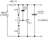
The last cap should be Os-con (the one that looks on TDA or CS chip). Do not use cheap cap here because the sound is awfull. Also if You use TL431 try to experiment with adjusting the current through TL431 (by changing 44R resistor- it is working differently). Also before this regulator You can connect battery (12V) but change the 44R to a higher level. If You use LM317 in fornt of that TL431 regulator BEWARE- LM317 sound- well- not very good- after the LM317 and before TL431 You should connect some good cap's - 330uF would be enough- but the also need to be very good. It is my humble opinion.
daniel
p.s. I am trying also to get green light out of my DAC and have the same problems as You have so the above opinion is few days of work old.
the latest - try battery with TL431 after
I have also tried batteries in my dac (CS8412CP & TDA1543N (1 chip). EVERYTHING is better- only the soundstage is little flat- but the reason for that could be something else- not the battery.
The last cap should be Os-con (the one that looks on TDA or CS chip). Do not use cheap cap here because the sound is awfull. Also if You use TL431 try to experiment with adjusting the current through TL431 (by changing 44R resistor- it is working differently). Also before this regulator You can connect battery (12V) but change the 44R to a higher level. If You use LM317 in fornt of that TL431 regulator BEWARE- LM317 sound- well- not very good- after the LM317 and before TL431 You should connect some good cap's - 330uF would be enough- but the also need to be very good. It is my humble opinion.
daniel
p.s. I am trying also to get green light out of my DAC and have the same problems as You have so the above opinion is few days of work old.
the latest - try battery with TL431 after
Attachments
- Status
- Not open for further replies.
- Home
- Source & Line
- Digital Source
- mains ps for DDDAC?