Schaffner specify the frequency response of the filter (<3 dB attenuation below 10 kHz rising 35 dB at frequencies above 1 MHz) for '50 Ohm/50 Ohm Sym' and '50 Ohm/50 Ohm Asym'.
Ermm... what does this mean? Is this the impedance assumed on the line side and amp side? What does sym(metrical) mean in this context?
Thanks Osvaldo.
50ohm/50ohm for source/load impedances
Asymmetrical is common-mode, symmetrical is differential-mode
Last edited:
50ohm/50ohm for source/load impedances
Most likely the LISN (Line Impedance Stabilization Network) test setup. This is a common filter test configuration. Unfortunately is seldom reflects real world situations.
Most likely the LISN (Line Impedance Stabilization Network) test setup. This is a common filter test configuration. Unfortunately is seldom reflects real world situations.
To measure a filter you need to have some terminating impedances. It is convenient if these happen to coincide with the impedance presented by most RF test gear. At other impedances the filter will probably still do something useful, but we don't know.
I made my own line filter inside a metal power strip, this way I choose the parts inside.
While I have considered the iec panel type, I don't know what is inside, and feel that I would regret it.
Still, these will just skim off the top of the noise, but not a bad "bang for the buck" improvement.
While I have considered the iec panel type, I don't know what is inside, and feel that I would regret it.
Still, these will just skim off the top of the noise, but not a bad "bang for the buck" improvement.
Anybody know what extent an electrostatic shield on a toroidal transformer (between primary and secondary windings) can attenuate noise conducted into the amp? Is this very effective/worth doing?
the screen/shield is a filter.
It is a CR where the C is the capacitance between primary and screen and R is the resistance/impedance from the screen to Chassis.
To be effective the capacitive reactance should be big and the connection impedance should be small and preferably very small.
But it's actually a T filter:
C from primary - R to chassis - C to secondary
If the R impedance is not infinitely small, then some of the original interference passes across the two series connected capacitors, effectively C/2 if the R impedance were infinitely big.
The effectiveness of the filter depends on the impedance to Chassis being very low.
That's why you must not use a long wire to some remote connection.
H.Ott describes this in his electromagnetic bible.
Some transformers use a dual screen. One is connected to Chassis and the second is connected to the receiving audio ground. Check your line level audio transformers, many have dual screens.
Last edited:
Thanks Andrew. Canterbury Windings made me a 100VA transformer with electrostatic screen. Can I connect this to a common/star ground point? Is that what you mean when you say chassis ground? Thanks again.
(I'm asking all my really dumb questions here under cloak of anonymity).
(I'm asking all my really dumb questions here under cloak of anonymity).
Last edited:
No, that is not what I meant.
Connect the screen direct to the Chassis where the screen cable comes out of the insulation.
Connect the screen direct to the Chassis where the screen cable comes out of the insulation.
Andrew
Screen or no screen, the chassis needs a return-path to absorb that primary-secondary coupling.
A turntable with "speed control and choppered drive motor" produced 6 microVolts
(measured on a 7A22 Tek plugin) of 60Hz in the Left-Right RCA cables, because the primary-secondary coupling at 117VAC caused that much I*R drop in the phonocables.
Only thing I could think to do was tie the 5th wire of the turntable to the Scope GND.
Again, the "chassis" needs a path somewhere, as you well know.
Advice on mains distortion filter needed.
Motivation: DIY Class A Amps with beefy CLCRC filtering always sound awesome. Beefy Denon AVR sounds awesome in the evening/night but shitty during the day. Tried isolation transformer on AVR with little effect during the day. Measured THD on the mains and found a significant difference day/night. Day: 2% THD mainly 3rd harmonic; night 1.2% THD distributed over 3rd 5th 7th harmonic. As there is a good correlation I´d like to get rid of the mains distortion.
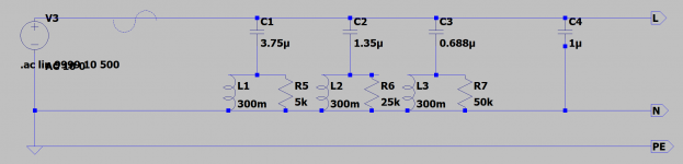
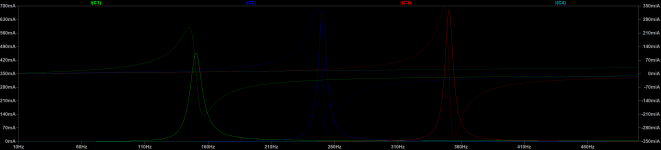
As I do not want to buy a regenerator to test this, I want to try a parallel notch filter for each odd harmonic first. Surpisingly I did not find any design like that, which might have a reason. Attached is a schematic with the notch filters. Of course caps will be line rated and the coils will be 1A rated (reactive current from fundamental 0,5A + 0,5A current at notch in case of 3% 3rd harmonic). I guess tuning the cap values to the inductors will be PITA.
Any comment is welcome.
Edit: no series element is a design decision (dynamics restriction etc.)
Motivation: DIY Class A Amps with beefy CLCRC filtering always sound awesome. Beefy Denon AVR sounds awesome in the evening/night but shitty during the day. Tried isolation transformer on AVR with little effect during the day. Measured THD on the mains and found a significant difference day/night. Day: 2% THD mainly 3rd harmonic; night 1.2% THD distributed over 3rd 5th 7th harmonic. As there is a good correlation I´d like to get rid of the mains distortion.
As I do not want to buy a regenerator to test this, I want to try a parallel notch filter for each odd harmonic first. Surpisingly I did not find any design like that, which might have a reason. Attached is a schematic with the notch filters. Of course caps will be line rated and the coils will be 1A rated (reactive current from fundamental 0,5A + 0,5A current at notch in case of 3% 3rd harmonic). I guess tuning the cap values to the inductors will be PITA.
Any comment is welcome.
Edit: no series element is a design decision (dynamics restriction etc.)
Attachments
Last edited:
Interesting to see your results of line measurements for day vs night.
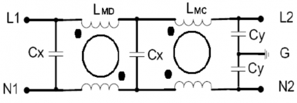
I use a simple filter inside a steel housed power strip. It’s just three .47uf line rated polypropylene caps across line and neutral with two chokes in between them. The chokes are wound with each line/neutral on either side of the cores, in opposing directions. I hadn’t measured the value of the common mode chokes, but it was maybe 7 passes over each side of each core. CLCLC.
Another thing that made a difference for me was to have a 2500 ohm, 100 watt resistor across line/neutral as well, on a 120v arrangement here in North America. This trick I picked up over on a ham radio forum a few years back. That person had been using a 15w light bulb, but I thought the resistor would be a bit more robust.
Just imagine how much noisy things are without all the incandescent bulbs the we used to have, replaced by bottom of the barrel switching supplies in each light socket.
Last edited:
Many thanks Phase. Sounds like you are running the usual EMC/EMI filter. I want to aim at 150, 250 and 350 Hz.
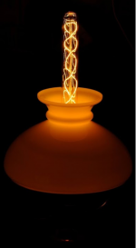
I missed the incandescent light bulbs so much, I bought a bunch of those fancy ones for my desk. Good idea to add a lamp as indicator for the harmonics being shunted 😀
I missed the incandescent light bulbs so much, I bought a bunch of those fancy ones for my desk. Good idea to add a lamp as indicator for the harmonics being shunted 😀
Attachments
braded ATX psu's like Enermax and HEC used a small board to implement a filter and is soldered right into the IEC power inlet, so what i do is to harvest them and use them in my tube amps....i feel better this way..
With a mains line impedance of 0,5 Ohms and earth impedance of 0,5 Ohms the filter reduces THD only by 10%. So it is a brain fart 😱
Filter yes, but definitely in an integrated IEC C14 inlet version - go toSimple question... I'm going to use a fused mains inlet from Schaffner and I just assumed the version with filter was the smart choice to reduce noise conducted into the amp.
It has since been suggested that it would be unwise to filter the mains.
What say you, learned folk? Filter or no filter?
Pops
Several components for hifi/home audio in used condition are danger even outside of operation, because the integrated capacitors in the mains inlet C14 plugs are not disconnect from mains after switch off the component (and not to check and for replace).
Therefore the aging is more extend and it is not possible to check the condition like describe under
because the parts are potted and thus not accessible without destroy.
A friend of me observe such...
Therefore the aging is more extend and it is not possible to check the condition like describe under
because the parts are potted and thus not accessible without destroy.
A friend of me observe such...
- tiefbassuebertr
- Replies: 23
- Forum: Power Supplies
- Home
- Amplifiers
- Power Supplies
- Mains inlet... to filter or not to filter?