Does the transformer look like this - with nothing in the middle?
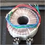
And then it mounts to the chassis with one bolt, the big washer, and a couple of rubber pads?

No, it's just a hole in the middle, a few mm in diameter, for a screw that didnt come with it. So Either I have to drill a hole and supply a screw and nut, or a couple of small striplocks.
Probably best to make the hole a bit bigger, get a long-enough bolt, fender washer, lock washer and nut.
That
Try to find out what thread they have used and buy a bolt to match.
Then simply bolt the transformer to the chassis with a compliant washer in between to avoid damage to the windings.
is almost certainly tapped.No, it's just a hole in the middle, a few mm in diameter,
Try to find out what thread they have used and buy a bolt to match.
Then simply bolt the transformer to the chassis with a compliant washer in between to avoid damage to the windings.
Thatis almost certainly tapped.
Try to find out what thread they have used and buy a bolt to match.
Then simply bolt the transformer to the chassis with a compliant washer in between to avoid damage to the windings.
It is. I'll bring it to the local hardware store and get the stuff.
It's tapped? That's great! All you need is a bolt and lockwasher + nut.
It has a locking thing on it, I think....I'll get the stuff next wek on a day off from work. I have been wreckingmy brain trying t fnd the best layout today...
Not easy deciding if the transformer goes to the righ or to the left from the regulatr 🙂
Can you make a sketch or post some photos??
My digital cam went "error" on me the other day, but I'll se if I can take some with the cellphone.
I think I have it figured out though. I'll keep the psu to the right, close to the power entry and the power in on the board, and I'll run the signal wires alongside the board, down the left side of the chassis and to the rca's.
Next time I am buidling something, I'll get a seperate psu enclosure, or if I only had done more research before buying the chassis for the B1, a wallwart. Live and learn / build nice or build twice 😛
It's all personal preference to use one or two enclosures. My most recent two-box projects would be nicer (IMO) if they were in one box.
Also, it depends on what mood you are in. Somedays I really like the 2-box approach, other days I want it all-in-one.
That's the best part about DIY - you are never really finished... 🙂
Also, it depends on what mood you are in. Somedays I really like the 2-box approach, other days I want it all-in-one.
That's the best part about DIY - you are never really finished... 🙂
It's all personal preference to use one or two enclosures. My most recent two-box projects would be nicer (IMO) if they were in one box.
Also, it depends on what mood you are in. Somedays I really like the 2-box approach, other days I want it all-in-one.
That's the best part about DIY - you are never really finished... 🙂
True.
How on earth do I connect the transformer to the power module and the regulator? The power entry isn't a "complete module" ie it isn't noxed with only the connectors for the power sticking out. I have to connect the on/off switch, the fuseholder and the iec inlet together in some way....didn't understand anything from looking at the datasheets....seems like bachelor-level stuff, and I am just out of kindergarden...
I really need help connecting this. I also would like to be able to understand why it has to be the way it has to be....
I really need help connecting this. I also would like to be able to understand why it has to be the way it has to be....
I can help you, but not on this forum, as I need to send pdf and such. Check your email.
Last edited:
- Status
- Not open for further replies.
- Home
- Amplifiers
- Pass Labs
- MagnumOpus & The B1