After a long and painful search for hum, I finally found that I am getting magnetic coupling between a power transformer and some output transformers. It is very low, so low that you can't really hear it during the day, but a night it is there. I found that moving the power transformer back about 3 inches is enough to eliminate the hum -- problem is that 3 inches is off the chassis. Everything is already at right angles, etc.
So, either I need to find some clever method of shielding, or I need to build a new chassis which I definitely do not want to do. So, is there some method to add a magnetic shield to the power and/or output transformers? Maybe some mu metal bell ends, or a way to pot them? Thoughts?
So, either I need to find some clever method of shielding, or I need to build a new chassis which I definitely do not want to do. So, is there some method to add a magnetic shield to the power and/or output transformers? Maybe some mu metal bell ends, or a way to pot them? Thoughts?
You might try picking up a metal basket at The Container Store. They have various sizes. Choose one made of steel of course. The ones I've seen there are painted, usually silver or black.
You can mount them to the chassis using plastic wire clips, the kind that form a loop and have a hole for a screw to go through. I used them in one project. I decided to use them for cosmetic reasons, open frame OPTs look ugly to me and these would mostly hide them while also preventing fingers from touching the B+ connection on the trafos.
I initially mounted the OPTs much closer to the PTX and had hum in the left channel. Dropping the basket over both OPTs "cured" the hum. I was surprised since they are baskets with 1/8" openings between the steel weave. I eventually moved the OPTs about 1.5 inch farther from the PTX and the hum is gone even with the basket off. The basket is still used for aesthetics though.
dsavitsk,
With a picture of your amp and a mention of the chassis material I can begin to help.
Just for starters, did you orient the OPT 90 degrees from the power, in three axis? If so, then airborne EMF coupling can almost be ruled out. If your chassis is non ferrous and the transformers are decoupled in three axis, then it is very likely due to antenna effects from the wiring. Perhaps the power rectification circuit is coupling with either the OPT leads or coil orientation.
Bud
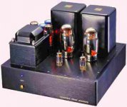
The amp can be seen at http://www.ecp.cc/semha.html
As you can see, transformers are 90 degrees, but slightly off axis -- to be fair, I was warned that this could be problematic, but there really isn't anywhere else to put them. After redoing nearly every part of the amp, I removed the power transformer, placed it far away and ran some long wires to it. This solved the problem completely. I also oriented it as if flush mounted and put it right behind the chassis and again silent. However, maintaining the flush mounting orientation but setting it right where it is, there is still some hum -- maybe a little less, but it is still there. Maybe this transformer radiates more than others (I have a Hammond with the same specs to try to see if this is correct), but I think I either need a shield, or a bigger chassis.
As you can see, transformers are 90 degrees, but slightly off axis -- to be fair, I was warned that this could be problematic, but there really isn't anywhere else to put them. After redoing nearly every part of the amp, I removed the power transformer, placed it far away and ran some long wires to it. This solved the problem completely. I also oriented it as if flush mounted and put it right behind the chassis and again silent. However, maintaining the flush mounting orientation but setting it right where it is, there is still some hum -- maybe a little less, but it is still there. Maybe this transformer radiates more than others (I have a Hammond with the same specs to try to see if this is correct), but I think I either need a shield, or a bigger chassis.
That is what I mean by flush mount orientation, which didn't help. The measured hum, if you can trust my DMM, is ~300uV. Low, but not quite low enough here.
dsavitsk,
What you have is only a single axis of rotation. If you laid the transformer on it's side and pointed the short side at the OPT's that would be very close, with two axis of rotation. Then rotation of the OPT's from vertical to horizontal mounting, still with mounting end bells, would be the last test for compatibility.
You can shield the core of the power transformer. You need at least grain oriented M6 applied over a layer of thin, two sticky side tape, with the overlap on top, if the chassis plate is steel and down if it is aluminum. Ideally the material width you use should extend beyond the core stack edges by about .050" on either side.
You can also wrap a copper shield around the coil and up over the laminations and core field suppression band. This is a shunted shorted turn and likely should be grounded at the power ground point.
If you look for the hum with a scope attached, look at power lead outs and surface of endbells and core with a sniffer coil. Look for spikes in the sine wave. A leading edge spike comes from the coil and a trailing edge spike from the core. You may also be able to find these at the OPT.
I do have some M6 shield stock already cut to size for specific transformers. If we have similar sizes you may be able to use it. If not, Lamination Specialties in Chicago and Yates Electro-Magnetics on the East coast, will usually cut to order. Also investigate the conetic alloys of Mu Metal that are available. You can purchase a "samples" set of sheet stock, but I no longer remember from whom. The cut to size strips of M6 will likely be cheaper.
Another avenue is a 0.060 thick CRS box, that has been heat treated to marstenite/osteonite temperature, to render it dead soft after forming the box. This will provide 100% EMF containment, even with constant voltage transformers.
Bud
BudP said:What you have is only a single axis of rotation. If you laid the transformer on it's side and pointed the short side at the OPT's that would be very close, with two axis of rotation. Then rotation of the OPT's from vertical to horizontal mounting, still with mounting end bells, would be the last test for compatibility.
Okay, I see. I'll give this a try and see if it helps.
BudP said:You can shield the core of the power transformer. You need at least grain oriented M6 applied over a layer of thin, two sticky side tape, with the overlap on top, if the chassis plate is steel and down if it is aluminum. Ideally the material width you use should extend beyond the core stack edges by about .050" on either side.
You can also wrap a copper shield around the coil and up over the laminations and core field suppression band. This is a shunted shorted turn and likely should be grounded at the power ground point.
The transformer is custom made, so I will call the maker on Monday and see if he can do some, or all of these things to this transformer. It is certainly the easiest option from my perspective, as realignment will require a new top plate, and otherwise a new chassis.
BudP said:Another avenue is a 0.060 thick CRS box, that has been heat treated to marstenite/osteonite temperature, to render it dead soft after forming the box. This will provide 100% EMF containment, even with constant voltage transformers.
Any idea where to get such a box?
dsavitsk said:Okay, I see. I'll give this a try and see if it helps.
Nope. The hum might be slightly lower, but not appreciably.
Your hum predicament reminds me of a repair/modification I had not long ago with a friends custom headphone amplifier. His unit worked flawlessly and dead quite for quite a while. Then one day it began humming in the phones at a very low level. When the original builder was unable to fix it, he brought it to me.
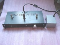
After checking many or the usual suspect things like power supply filters, wiring, lead dress, tubes etc, I realized it was the power transformer itself. Remember, it once was dead quiet. The hum appeared the instant power was applied. Even without the tubes in place and no amount or type of shielding helped. Copper wrap, steel boxes, even beer cans did nothing. (I didn't have any mu-metal to try) The small output transformers were underneath the steel chassis.
The power transformer was a commercially built double shell vertically mounted unit The core was tight as well as the laminations, and it was varnished and baked. Finally I removed the four mounting screws from the power trans so I could rotate it. That made it slightly worse which told me it was originally positioned correctly.
Lifting the transformer up as far as the leads would allow and leaning it backward off the rear apron reduced the hum to almost zero as heard in the headphones. I then removed the unit for further testing. Hypoting to 500v (AC & DC) between both windings and winding to core showed no leakage. Unloaded quiescent primary current from core loss seemed about normal at around 20+ ma. A hand held magnetometer passed around the transformer showed only minimum indications. And a ring test with a scope of the HV secondary was inconclusive mostly because power transformers don't ring well even with low pulse rates.
So the outcome came down to either replacing an otherwise perfectly good transformer (which I didn't have), or mounting it external to the amplifier. We chose the latter option. I believe that some (very few) transformers can produce hum no matter what for some crazy reason. You may have a similar situation.
Victor
Attachments
In general:
One of the culprits in steel chassis is that flux will wander down the bend radius that forms the box. It then will emit at some point determined strictly by Murphy, except that it is always aimed just right somehow. Very narrow fans of radiation. That is what the heat treating eliminates.
dsavitsk,
George Wright always raises both power and output transformers off of the chasssis, sometimes as much as a quarter inch. But, he uses steel chassis too.
That thick CRS will have to be bent by someone with powered sheet metal bending equipment. I have no doubt you can find someone to do this for you and since you have two lamination companies in town, one of whom (Tempel Steel) used to heat treat endbells for me.... ok, it was 30 years ago, but they were always accommodating and friendly. You could call Tom Thomas at Tempel and see if he can provide some help after you get a box formed and welded up, but before you commit to getting the box made. He is the Magnetician at Temple and a fine fellow indeed.
Final possibility is getting a low stray field power transformer made. Something around 6 to 7 kilogauss should do the trick. And, you do live in transformer central, so there are many culprits to contact.
As you are finding, this is not an easy problem to solve!
Bud
My luck with shielding transformers has been pretty bad, as you need full coverage with dead soft steel or mu metal, which is rarely practical for me. Here's a trick that might or might not have an effect. If you can find yourself some thick aluminum jig plate, at least 5/8", drop a piece of that between the transformers. Above a certain thickness, the eddy current losses of aluminum are quite effective at killing magnetic interference. It sounds a bit nuts at first, but I've solved some very low level interference problems exactly that way.
- Status
- Not open for further replies.
- Home
- Amplifiers
- Tubes / Valves
- Magnetic shields for transformers