Hi, vintage inquiry here...
Magnetic Reed Switches:
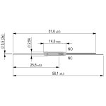
Single Pole, Double Throw.
The common lead toggles between two contacts:
Normally Open (N.O.) and Normally Closed (N.C., longer lead).
image example only

On the dual throw part of the above magnetic reed switch;
The through metal leg is Normally Open
The compound metal leg is Normally Closed
Common contact, the switcher (out of pic)
IF this corresponds to the broken one in the image below it would mean that the long lead would be N.C. and the shorter lead would be N.O.
This is the one to identify-


Is there a standard by which the N.C and N.O. are attributed to a length of leg?
E.G. Lytic Capacitors have the long leg to identify positive.
Coil houses two Magnetic Reed Switches mounted symmetrically. Both failed, one removed, shown below-

This is the circuit that the broken switch was removed from-

BCY70
BC107
100µF
Magnetic Reed Switches:
Single Pole, Double Throw.
The common lead toggles between two contacts:
Normally Open (N.O.) and Normally Closed (N.C., longer lead).
image example only
On the dual throw part of the above magnetic reed switch;
The through metal leg is Normally Open
The compound metal leg is Normally Closed
Common contact, the switcher (out of pic)
IF this corresponds to the broken one in the image below it would mean that the long lead would be N.C. and the shorter lead would be N.O.
This is the one to identify-
Is there a standard by which the N.C and N.O. are attributed to a length of leg?
E.G. Lytic Capacitors have the long leg to identify positive.
Coil houses two Magnetic Reed Switches mounted symmetrically. Both failed, one removed, shown below-
This is the circuit that the broken switch was removed from-
BCY70
BC107
100µF
Background:
The magnetic reed switch was invented in 1922 by professor Valentin Kovalenkov at the Petrograd electrotechnical university and later evolved at Bell Telephone Laboratories in 1936 by Walter B. Ellwood into the reed relay. His original patent application for an electromagnetic switch was filed on june 27, 1940 and officially granted on december 2, 1941. Reading through Elwood's patent, it's easy to recognise the reed switch that's still in common use today:
"when an external magnetic force is applied to this unit the two magnetic members which form part of the magnetic circuit... are moved together... since the external magnetic force acts to diminish the air-gap between the two said magnetic elements."
If you look at the images of the new and failed, both have a straight contact and a compound contact.
It's a fair assumtion that the contact situation is the same.
I am not aware of a lead length difference to show contact situation, but there's many things I don't know...
Edit: the attached shows short for NO. Standex-Meder. Google is your friend ...
You have a schematic?
Jan
It's a fair assumtion that the contact situation is the same.
I am not aware of a lead length difference to show contact situation, but there's many things I don't know...
Edit: the attached shows short for NO. Standex-Meder. Google is your friend ...
You have a schematic?
Jan
Attachments
Last edited:
Same as my first thoughts, the compound metal side probably being an anti arc metal compounded to the external longer lead.If you look at the images of the new and failed, both have a straight contact and a compound contact.
It's a fair assumtion that the contact situation is the same.
The first three images look like the same manufacturer too.
I was hesitant because there is no evidence of arcing on the failed switch, probably due low voltage of 12V and low current.
Thanks for the diag, another correlation that the long lead is N.C.
