Magnetic Circuit Guru's Needed
Ok..I’ve collected enough basic info on my wingnut powdered core experiment, that I think someone with more magnetic circuit knowledge than I have could ballpark its potential Mu performance.
I buried a coil measuring 1.7”D x 2.3”L with 150 turns in a Styrofoam cup in loose filled iron powder with a density (mass) of approx 60% of solid iron (.4 air gap ratio). Measuring inductance before and after filling, I got a Mu of around 2.5. After shaking the cup to settle the powder a little better it went up to 3.5. I then pressed the iron with my palm with around 5psi (its in a Styrofoam cup, so I can’t push hard) it bumped up to 5. So, increasing the effective mass (or, reducing the airgap ratio) by, at most, 2% doubled the Mu.
I realize I’m only looking at a few ballparked data points here, and my knowledge of magnet circuit theory is , to make an understatement, rusty, but if it follows that decreasing the airgap ratio 2% doubles the Mu, wouldn’t dropping it 4% increase it by 4, 6% by 8, 8% by 16 ect. ect.? The texts I’ve seen deals in air gaps of between .1% and .2%, so I realize the ratios I’m playing with are huge by comparison.
Any and all input would be appreciated.
Casey
law of diminishing returns
I wouldn't call myself any magnetics guru, but I think the initial gains in Mu versus pressure will drop off as pressure increases. This being due to the easy stuff moving and squeezing first. But before long the stuff will have to deform in order to get a better fit and that will take significant pressure (ie. hydraulic). Once you pass a certain point, most of the surfaces will have squashed together and further gains will require massive pressure to get very small gains. So the curve will look something like the RC time constant decay curve with asymptotic approach to 100% density versus pressure.
My 2 cents.
Don
The maximum of course being HIPing, only a little difficult (and probably a bad core result) in the garage. 😉
Tim
Tim
HIP = hot isostatic pressing
wonder what happens if you put the iron powder in a microwave oven, Hmmm, maybe fireworks!
Another idea, how about filling in the gaps with a ferrite like material at high temperature. Borax dissolves metal oxides well, it's used as a welding flux, so try mixing crushed ferrite core powder with borax and the iron powder. Then heat it all up with a torch until it all melts down to a solid.
Don
Mmm, liquid phase sintering...
Should form a relatively insoluble sodium iron borate glass, so that'd probably work. Mind that dodecahydrates are unfriendly on heating! 😀
A smidge of clay would probably work well too, making something of a spinel mixture, which I seem to recall is somewhat magnetic also? Has to be done hotter though. Maybe wrapping in a borax glaze would prevent the iron from oxidizing to plain old ferrite. 🙂 Whaddya know, powdered iron and enamel coating in one step!
Tim
I realize I’m only looking at a few ballparked data points here, and my knowledge of magnet circuit theory is , to make an understatement, rusty, but if it follows that decreasing the airgap ratio 2% doubles the Mu, wouldn’t dropping it 4% increase it by 4, 6% by 8, 8% by 16 ect. ect.? The texts I’ve seen deals in air gaps of between .1% and .2%, so I realize the ratios I’m playing with are huge by comparison.
If you still intend to use a plastic binder, it probably won't go much higher than 5.
$.02
John
Once you pass a certain point, most of the surfaces will have squashed together and further gains will require massive pressure to get very small gains. So the curve will look something like the RC time constant decay curve with asymptotic approach to 100% density versus pressure.
Sounds reasonable enough, but isn’t the reverse effect true when dealing with conventional air-gaps, ie, as the gap decreases the Mu rises exponentially? That seems to be the case with the charts/graphs I’ve seen. It does beg the question though as to what makes the bigger difference, contact area size, or total distributed air-gap. Hmmm…
hot isostatic pressing
Mmkay…I’m trying to keep my process fairly simple. If I cant do it with a hydraulic press and glue, I probably (notice I didn’t say wont) do it.
If you still intend to use a plastic binder, it probably won't go much higher than 5.
Why would that be? As I understand it, flux lines behave the same whether they’re passing through air, cardboard, plastic, wood, mylar, whatever. Now, its entirely possible I will never reach a useable Mu, but why would epoxy guarantee failure? An “air-gap” of X dimension is still an “air-gap” of X dimension even if it filled with something other than air. Even “normal” transformers often use plastic shims in the gap.
Casey
maybe the graphite is useful!
Hi Valveitude,
Hows things going with the powdered iron tranny?
I was just thinking the other day about a retro amplifier device and then realized you have got just the right materials to make one. Remember the old graphite disk voltage regulators? These were often used to control the field winding current on generators. I remember one I took apart once. It had a pile of carbon disks stacked in the center round bore hole of a cylindrical finned aluminum heat sink. It had an electromagnetic actuator on one end to compress the disks. The carbon disk pile had metal disks with wires on its ends, which then acted as a variable resistor as the pressure on the disk pile was varied.
Now, suppose we combine the graphite powder and magnetic powder together, maybe with a soft elastic binder, and apply a magnetic field to the whole thing. As the field increases, the stuff contracts and resistance drops. If the time constant of this can be made fast enough, we have a potential amplifier with low output impedance. Might be noisy, but then telephones used to use essentially the same idea for carbon mics. Probably can lower noise by using more material in parallel. Maybe can add powdered copper to the mix too to lower resistance.
Another possibility might be to use piezoelectric or magnetostrictive actuators to control the pressure on the material. Probably would want to apply the pressure to a thin film of material at right angles to the resistive current flow channel.
Don
🙂
let the force be with you... just whack the core with some unfiltered rectified AC and beat it into summission.
just last night, i wass trying to get a nice small butt gap in a pair of autoformers stacked with 80% nickel. the most inductance i could get with clamping was 18hy, but passing a 100maDC through the coil (5ma saturates it!) and whacking the whole thing with the end of a screwdriver pulled everything together and netted me 25hy a full 20% more than i have ever seen from this arrangement.
the DC will provide the pressure, and the AC will shake it.... its worth a quick test.
dave
The Iron Powder Journey Ends...For Now
Hi smoking-amp,
We-l-l-l , a couple things have occurred to change my direction, first, I mentioned early on that this project’s cost was an “economy of time”…it got too expensive. I did make some interesting progress though. A happy accident gave me the perfect binder. A couple of days after a good rain, I went out to work with the powder I had laid out in a sheet to dry to discover that a) I had a new roof leak, and b) it was directly over my powder. After I stopped cursing, I checked to see how much was salvageable. Most of it looked ok, but the water had wicked through it and oxidized it into a solid mass. I measured its resistance, and it was over a meg …hmmm.
A made a mold out of a coke can lined with cheesecloth, and buried a coil in loose filled powder in the mold. I then slowly added water until it started dripping out the bottom, then I knew it was fully saturated., I then removed the aluminum , leaving the iron ‘mud in the cheesecloth. This was baked at 180deg for 6 hours and this is what I got…
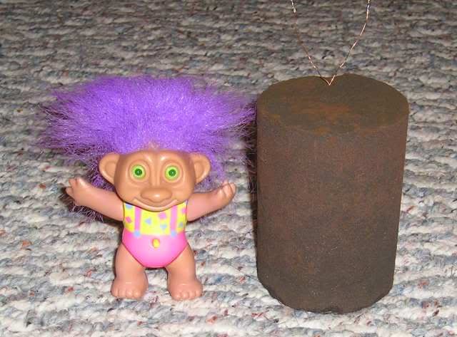
… it has a mu of ~4.3, around 75% up from loose filled dry. I am convinced with the right mold and pressure it could reach into the hundreds, but I am also convinced that the effort involved is just to much . I could build a couple complete amps for the same amount of energy. I did get a lot out of the process though, a spiffy ball mill, enough powdered iron to make one hell of a bar antenna for another hobby (my Transoceanic H-500), a lot of gained knowledge, and oh ya, the graphite.
If you want to give it a go, email me and I can work out getting you some.
Another discovery that led me away from brake chips, is my dream speaker for SE. I have been a ribbon nut for a long time, but the low efficiency has kept me away…until now. Check out this thread…
http://www.diyaudio.com/forums/showthread.php?s=&threadid=50162&perpage=10&pagenumber=1
and his site…
http://home.comcast.net/~hendentures/index_files/Page332.htm
Bottom line, he made a .5”x36” ribbon with 95db@1 watt, usable down to 500 easy (with a questionable transformer). But wait, it gets better. Using the magnetic modeling software that he links to,”Femm”, I’ve come up with a dual .75 ribbon with a projected effeciency of 100db@1 watt !!!
I think I can live with a smaller amp
Later,
Casey😀
Hi smoking-amp,
Hows things going with the powdered iron tranny?
We-l-l-l , a couple things have occurred to change my direction, first, I mentioned early on that this project’s cost was an “economy of time”…it got too expensive. I did make some interesting progress though. A happy accident gave me the perfect binder. A couple of days after a good rain, I went out to work with the powder I had laid out in a sheet to dry to discover that a) I had a new roof leak, and b) it was directly over my powder. After I stopped cursing, I checked to see how much was salvageable. Most of it looked ok, but the water had wicked through it and oxidized it into a solid mass. I measured its resistance, and it was over a meg …hmmm.
A made a mold out of a coke can lined with cheesecloth, and buried a coil in loose filled powder in the mold. I then slowly added water until it started dripping out the bottom, then I knew it was fully saturated., I then removed the aluminum , leaving the iron ‘mud in the cheesecloth. This was baked at 180deg for 6 hours and this is what I got…
… it has a mu of ~4.3, around 75% up from loose filled dry. I am convinced with the right mold and pressure it could reach into the hundreds, but I am also convinced that the effort involved is just to much . I could build a couple complete amps for the same amount of energy. I did get a lot out of the process though, a spiffy ball mill, enough powdered iron to make one hell of a bar antenna for another hobby (my Transoceanic H-500), a lot of gained knowledge, and oh ya, the graphite.
I was just thinking the other day about a retro amplifier device and then realized you have got just the right materials to make one.
If you want to give it a go, email me and I can work out getting you some.
Another discovery that led me away from brake chips, is my dream speaker for SE. I have been a ribbon nut for a long time, but the low efficiency has kept me away…until now. Check out this thread…
http://www.diyaudio.com/forums/showthread.php?s=&threadid=50162&perpage=10&pagenumber=1
and his site…
http://home.comcast.net/~hendentures/index_files/Page332.htm
Bottom line, he made a .5”x36” ribbon with 95db@1 watt, usable down to 500 easy (with a questionable transformer). But wait, it gets better. Using the magnetic modeling software that he links to,”Femm”, I’ve come up with a dual .75 ribbon with a projected effeciency of 100db@1 watt !!!
I think I can live with a smaller amp
Later,
Casey😀
- Status
- Not open for further replies.
- Home
- Amplifiers
- Tubes / Valves
- Magnetic Circuit Gurus Needed