It looks like it uses a tube type preamplifier section.
A mag amp cannot be made to work well as an audio power amplifier. It's not because of circuit design, it's because of basic physics.
A mag amp cannot be made to work well as an audio power amplifier. It's not because of circuit design, it's because of basic physics.
You're wrong.
The fellow who made the simple DIY style mag-amp site
also demonstrated the audio amplification properties in a video on youtube.
It sounded quite good, and that example was made out of junk. It was a rickety proof of concept arrangement.
His circuit was very primitive. I'm going to make one out of good quality components, and the circuit I will be building is alot more complex and has a many improvements.
A good magnetic amplifier acts like a switch. The bias current puts a magnetic bias in the core. This bias determines how many volt seconds can be applied to the power winding. After the volt seconds has been reached the core saturates and the power winding inductance (impedance) becomes very small. So the voltage, across the load is sort of a chopped sine wave; or a sine wave with a portion of the signal at zero. This is somewhat oversimplified, but you should get the idea.
I'll be interested to see what you come up with, but I'm skeptical.
I'll be interested to see what you come up with, but I'm skeptical.
A good magnetic amplifier acts like a switch. The bias current puts a magnetic bias in the core. This bias determines how many volt seconds can be applied to the power winding. After the volt seconds has been reached the core saturates and the power winding inductance (impedance) becomes very small. So the voltage, across the load is sort of a chopped sine wave; or a sine wave with a portion of the signal at zero. This is somewhat oversimplified, but you should get the idea.
I'll be interested to see what you come up with, but I'm skeptical.
It works, and it's cool old retro technology which is dragged into the future and dusted off. Today I bought a matched pair of brand new
120v to 14v transformers. I'm compiling a parts list for tomorow for the ither things. Right now I am building a monophonic prototype. I'll keep you and everybody posted. I'm as interested in the outcome as you and everybody else is.
Magnetic amplifier
Hello CivicProtection. I've had a look at this way back and did some experiments with AC mains 1:1 and step up/down transformers ... it really is interesting. I based my knowledge on white paper "Magnetic Audio Frequency Fundamentals" I think it was called. Worth a read, I'll have a look if I still have it. If you / you people are interested.
Hello CivicProtection. I've had a look at this way back and did some experiments with AC mains 1:1 and step up/down transformers ... it really is interesting. I based my knowledge on white paper "Magnetic Audio Frequency Fundamentals" I think it was called. Worth a read, I'll have a look if I still have it. If you / you people are interested.
Reference my previous post:
I've just done a web search and found the document; heres the link to a pdf.
http://www.aes.org/aeshc/pdf/how.the.aes.began/vincent_magnetic-audio-fundamentals.pdf
Maybe I should have done this first?
I've just done a web search and found the document; heres the link to a pdf.
http://www.aes.org/aeshc/pdf/how.the.aes.began/vincent_magnetic-audio-fundamentals.pdf
Maybe I should have done this first?
This simplified schematic was featured in a German Magazine article that introduced the original Lundahl Magamp in 1996.
Unfortunately, I didn't save the .pdf or a link to it and I can't seem to find it anymore.
Edit: Found it!
http://www.auditorium23.de/MagAmp/MagAmp.pdf
An externally hosted image should be here but it was not working when we last tested it.
Unfortunately, I didn't save the .pdf or a link to it and I can't seem to find it anymore.
Edit: Found it!
http://www.auditorium23.de/MagAmp/MagAmp.pdf
Last edited:
Could someone briefly explain how the signal modulation in the Lundahl MagAmp works, please? I can't wrap my head around that thing no matter how hard I try and SPICE simulations aren't exactly helpful if you want to simulate a transformer with a saturating core.
Mag amps were used in the early days of long wave radio. An example is Grimeton Radio, starting operation on December 1st, 1924 on 17.2 kHz. Those early day transmitters used Alexanderson alternators. Those are AC alternators that generate the radio frequency. The signal then gets modulated by a choke like in an arc welder. I think that choke is called "Poulsen coil" or something.
@teemuk: I didn't understand the Lundahl amp principle, too. It looks to me like it could never operate at all.
@teemuk: I didn't understand the Lundahl amp principle, too. It looks to me like it could never operate at all.
Had a bit of fun at the Bench last night.
YouTube - Saturable Reactor
Also, possibly the largest saturable reactor you'll see on this forum...
I'll get the schematic along later.
Tim
YouTube - Saturable Reactor
Also, possibly the largest saturable reactor you'll see on this forum...
I'll get the schematic along later.
Tim
AcousticPlans Magamp was demontrated at the HighEnd im Munich. This is a slightly modified/improved Lundahl magamp. Under the circumstances given it sounded nice. If you consider that most of the sound produced at the HighEnd was lousy the performance was quite all right. So it does work.
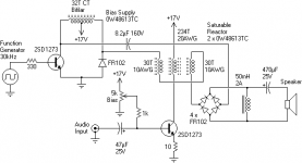
I have an idea Temuk.... watch my schematic..it is the same schematic
drawn different.... seems to me a modulation process...anything complicated there...if you are not an engineer and do not want formulas or description of saturation process, i can explain you almost 95% of how this works.
I can understand the same way people understand electron and nobody could see electron..we know how electrons works... also i know how this works.
Modulation and demodulation is what you have.... there's 1,2,3 numbers pointing positions where you have these signals (more or less this way)....at rigth the signals....1 is modulated, 2 is rectified and 3 is the audio signal after filtering..an filtering here is the 30 kilohertz carrier drained to ground througth the choque, the inductor that took a sophisticated name of saturated core and so on.
First stage, the one receive the square wave pilot signal, is a not perfectly tuned 30 kilohertz amplifier that will be modulated by the audio transistor.
I think you already understood...if not..send me an email and then i will have your personnal email adress.... this way i will be able, tomorrow (more 8 hours) to send you an audio file (MP3) and some sketches, explaining how this works.
carlos.eugenio1951@yahoo.com
Radio amateurs...all them..will understand this very fast...if you have one in your surroundings, talk with him in your own language and he will exterminate all this mistery, and very fast.
I suppose, watching my simplified and non tricky schematic, you will already understand..the mistery is the way was drawn.
regards,
Carlos
Attachments

Last edited:
The problem is with the choke across the output of the bridge rectifier. You do have to rectify the modulated HF at the output to retrieve the audio, but that gives a high level of DC along with the audio.It does clip easily though.
Unfortunately you can't get rid of the DC by just shorting it with a choke. Doing it properly requires some extra complexity, as with the Lundahl amp.
btw: The key to the Lundahl amp is that the cores go in and out of saturation at HF, but the "depth" of saturation of the various cores depends on the audio signal.
~~~~~~~~~~~~~~~~~~~~~~~~~~~~~
I like that it works with a HF square wave. That means the HF generator can be rugged and high efficiency. If core losses are also small, then a mag-amp should be able to reach overall efficiency similar to class D amps.
I know a choke across a bridge will simply short out the negative-going phase. But this does not explain how I was getting any signal at all. 🙂
Turns out, the particular choke I was using was quite resistive, and had about 20V across it under best operating conditions!
I replaced it with a 10 ohm wirewound resistor (optionally in series with a much lower resistance 50mH choke), which allowed more power output.
The heavier load necessitated some changes:
Instead of connecting the reactor across the ends of the AC bias transformer, only half was used (i.e., 2SD1273 collector and the CT).
Since current was getting quite large, I switched from 2SD1273 to a 50N06 MOSFET; I also added an RCD snubber to protect it from voltage spikes. (The spikes got so large (~70V, with currents up to 5-10A for pulses of maybe 1us), I blew up two electrolytic capacitors trying to contain it. I ended up with an 8.2uF film cap, which served admirably.) These changes are shown here:
I also found some peculiar results.
While a square wave is convienient, if its harmonic content changes, the sound changes. For instance, while operating at less than 50% duty cycle, the bias supply creates a square "bottom" (while the MOSFET is turned on), followed by a fairly square peak (the opposing FR102 conducting), followed by dead time with ringing. Well, the amount of ringing present depends on the load, which is dynamic. In fact, it seems to feed back in a very nonlinear fashion, resulting in apparently repeating traces: for instance, under some conditions, every other cycle might have an alternating magnetization, causing the ringing to be faster on one cycle and slower on the next. On the 'scope, you see the illusion of two ringdowns during this period (or you see them seperately if you adjust holdoff to stabilize the image). Under other conditions, 3 or more different ringdowns may be visible. Indeed, the number of combinations seems to increase exponentially, so that most of the range, a random ringdown seems to be picked -- generating mild white noise as a result. A clear example of a chaotic system, with all that classical bifurcation and indeterminate evolution stuff!
I also tried a self-biased reactor, by replacing the bridge rectifier with a single diode (I used a spare MUR2020). This had acceptable results, with the main difference being peculiar nonlinearities (while varying bias, there seem to be multiple regions of minor linearity, seperated by fairly distorted regions -- the transfer curve must be pretty kinky).
I also observed hysteretic behavior, where the self-biased output kept itself magnetized, but only for sufficiently high bias currents. While in this state, a much lower value of control bias was necessary to restore the "normal" operating point, illustrating hysteresis.
Tim
Turns out, the particular choke I was using was quite resistive, and had about 20V across it under best operating conditions!
I replaced it with a 10 ohm wirewound resistor (optionally in series with a much lower resistance 50mH choke), which allowed more power output.
The heavier load necessitated some changes:
Instead of connecting the reactor across the ends of the AC bias transformer, only half was used (i.e., 2SD1273 collector and the CT).
Since current was getting quite large, I switched from 2SD1273 to a 50N06 MOSFET; I also added an RCD snubber to protect it from voltage spikes. (The spikes got so large (~70V, with currents up to 5-10A for pulses of maybe 1us), I blew up two electrolytic capacitors trying to contain it. I ended up with an 8.2uF film cap, which served admirably.) These changes are shown here:
An externally hosted image should be here but it was not working when we last tested it.
I also found some peculiar results.
While a square wave is convienient, if its harmonic content changes, the sound changes. For instance, while operating at less than 50% duty cycle, the bias supply creates a square "bottom" (while the MOSFET is turned on), followed by a fairly square peak (the opposing FR102 conducting), followed by dead time with ringing. Well, the amount of ringing present depends on the load, which is dynamic. In fact, it seems to feed back in a very nonlinear fashion, resulting in apparently repeating traces: for instance, under some conditions, every other cycle might have an alternating magnetization, causing the ringing to be faster on one cycle and slower on the next. On the 'scope, you see the illusion of two ringdowns during this period (or you see them seperately if you adjust holdoff to stabilize the image). Under other conditions, 3 or more different ringdowns may be visible. Indeed, the number of combinations seems to increase exponentially, so that most of the range, a random ringdown seems to be picked -- generating mild white noise as a result. A clear example of a chaotic system, with all that classical bifurcation and indeterminate evolution stuff!
I also tried a self-biased reactor, by replacing the bridge rectifier with a single diode (I used a spare MUR2020). This had acceptable results, with the main difference being peculiar nonlinearities (while varying bias, there seem to be multiple regions of minor linearity, seperated by fairly distorted regions -- the transfer curve must be pretty kinky).
I also observed hysteretic behavior, where the self-biased output kept itself magnetized, but only for sufficiently high bias currents. While in this state, a much lower value of control bias was necessary to restore the "normal" operating point, illustrating hysteresis.
Tim
Bump 🙂 Magnetic amplifier - Wikipedia
Homemade Magnetic Audio Amplifier.
Ebook in public domain https://www.rsp-italy.it/Electronics/Books/_contents/Magnetic amplifiers - Mali - 1960.pdf
US2868877A - All-magnetic audio amplifier system
- Google Patents
MagAmp
http://www.auditorium-23.de/MagAmp/MagAmp.pdf
Homemade Magnetic Audio Amplifier.
Ebook in public domain https://www.rsp-italy.it/Electronics/Books/_contents/Magnetic amplifiers - Mali - 1960.pdf
US2868877A - All-magnetic audio amplifier system
- Google Patents
MagAmp
http://www.auditorium-23.de/MagAmp/MagAmp.pdf
Great to see this thread revived.
Here is a surprisingly clear article:
The Magnetic Amplifier | Nuts & Volts Magazine
The 'Performance' section at the end is particularly interesting, and shows how versatile these devices are.
Here is a surprisingly clear article:
The Magnetic Amplifier | Nuts & Volts Magazine
The 'Performance' section at the end is particularly interesting, and shows how versatile these devices are.
- Home
- Amplifiers
- Solid State
- Magnet Amplifier (new info)