Gary P said:I have a very crude hand drawn schematic of what I found in one of these amps many years ago... One thing to look for is frequency shaping networks in the feedback network. It should be working nicely with the speakers that the amp was developed to run but you may want to remove them if you use the amp to drive different speakers.
Using Gary's schematic as a starting point i have recreated* it and added a few "comments".
In the map shown the red part is the feedback circuit (and maybe the orange 150k -- i'm not sure what it does). A pentode usually needs some feedback, so you could add "RH-style" feedback (blue) or strap in triode (remove the cyan and replace with the green triode strapping R),
I suspect that Gary missed a PS decoupling cap (Gray)
We can use this as a starting point for other suggested circuit changes)
dave
Gary, if you'd like a copy of this map for your web page (reverted back to match your sketch) just let me know
Attachments
I actually have a sams for this amp that I found searching the web before I bought it 🙂
Planet 10, it uses a 6EU7 as a driver tube. Also, the mullards sound sooo much better than the sovteks. Sovteks have thinner and flabbier bass, a little too much mid. The mullards are very well balanced, and have DEEP tight bass. The mids are more balanced on the mullards, and the highs are gorgeous with both tubes, I have heard things on tracks that I thought my ears just werent capable of hearing

Yes, the console its self sounds very good with the amp in it. I will obviously do some tweaking to this amp, but its a great place to start. I look at it as a hotrod- your never done with it, and you can drive it -er listen to it- while your working on it. 😉
Gary, what did your tubes test at? I finally tested mine, and the 6BQ5's are matched GM wise, both at 80, and both at 85 on the life test. The 6ca4 ( labled magnavox, japan) tested brand new (110) and the 6EU7 tested at 105.
Anatech: I gave it another listen, it is not exactly motorboating, it is hard to describe. You have to have the console turned all the way up to faintly hear very distorted and muffled fm reception when MPX is selected. It also sounds like it is underwater.
I will take apart the MPX section and see whats in there soon, but this unit seems to make generous use of ceramic disk caps as coupling caps.
Planet 10, it uses a 6EU7 as a driver tube. Also, the mullards sound sooo much better than the sovteks. Sovteks have thinner and flabbier bass, a little too much mid. The mullards are very well balanced, and have DEEP tight bass. The mids are more balanced on the mullards, and the highs are gorgeous with both tubes, I have heard things on tracks that I thought my ears just werent capable of hearing
Yes, the console its self sounds very good with the amp in it. I will obviously do some tweaking to this amp, but its a great place to start. I look at it as a hotrod- your never done with it, and you can drive it -er listen to it- while your working on it. 😉
Gary, what did your tubes test at? I finally tested mine, and the 6BQ5's are matched GM wise, both at 80, and both at 85 on the life test. The 6ca4 ( labled magnavox, japan) tested brand new (110) and the 6EU7 tested at 105.
Anatech: I gave it another listen, it is not exactly motorboating, it is hard to describe. You have to have the console turned all the way up to faintly hear very distorted and muffled fm reception when MPX is selected. It also sounds like it is underwater.
I will take apart the MPX section and see whats in there soon, but this unit seems to make generous use of ceramic disk caps as coupling caps.
Comments on the schematic...
The global feedback works pretty well on these little amps. For flat frequency response ditch both of the frequency shaping networks. There is a little (crude again) drawing in the lower left corner of the hand drawn schematic showing the frequency response with the networks in place.
The first network is a RC combo of the 33K and .1uf in the global feedback path. This network works as a bass boost/shelving network. It works by reducing the global feedback at lower frequencies. The bass boost starts at ~200Hz and levels off at ~50Hz. To remove the network connect the 8.2K feedback directly to the cathode of the input tube or just short the RC network out with a jumper wire.
The second network is the .047uf cap and the cathode resistor of the input stage. It works by shunting global feedback to ground at the higher frequencies. It boosts the treble starting at ~4K. To remove the treble boost just cut the .047uf cap out of the circuit.
The 150K resistor is a noise canceling scheme. Noise from the driver supply is injected into the feedback node to try and cancel the noise. Works pretty well in this circuit. When I disconnected the 150K resistor the amp had more background hum. Crude Aikido?
I don't remember what the original tubes measured at. I picked up the first amp 15 years ago... I do know that the same rectifier tubes are still in them after converting them to the David monoblocks.
Planet10, Thanks for the schematic offer. That would be much nicer than the crude had drawn version and I can be lazy and not draw it up myself. 😀
SpeakerDude, It would be interesting to know if the frequency shaping networks in the global feedback loop are in your amp and if they are the same of different values. Does the Sams make any notes about these?
Gary
I am not sure, I havent gotten the time to go over the two and compare. They might be completly different , since the schematic is for the one that includes the controlls on the amp, but they really are the same amp so I think it will be very close ( minus the tone controlls).
I finally got around to testing all the tubes in the radio section. Apparently the tubes are not original, they are almost all replacments except the output tubes and the rectifier.
They are as follows:
On the FM MPX chassis:
12AT7 (sylvania, black plates) =87/85
6ea8 (General Electric)= 60/110 ( I don't remember which side is the diode)
On the Tuner Chassis:
6AL5 ( Sylvania)=80/82
6BA6 ( Browning)=72
6BA6 (Sylvania)=85
6BE6 (Sylvania)=85
6DT8 (CBS)=62
These were all tested on my B&K 700.
I am wondering if the 6DT8 and the 6EA8 need replacing? They seem to test poor on the tester, would these make my FM MPx not work right? While I know plenty about tube amps, I don't know have any experience with the inner workings of an FM tuner.
😕
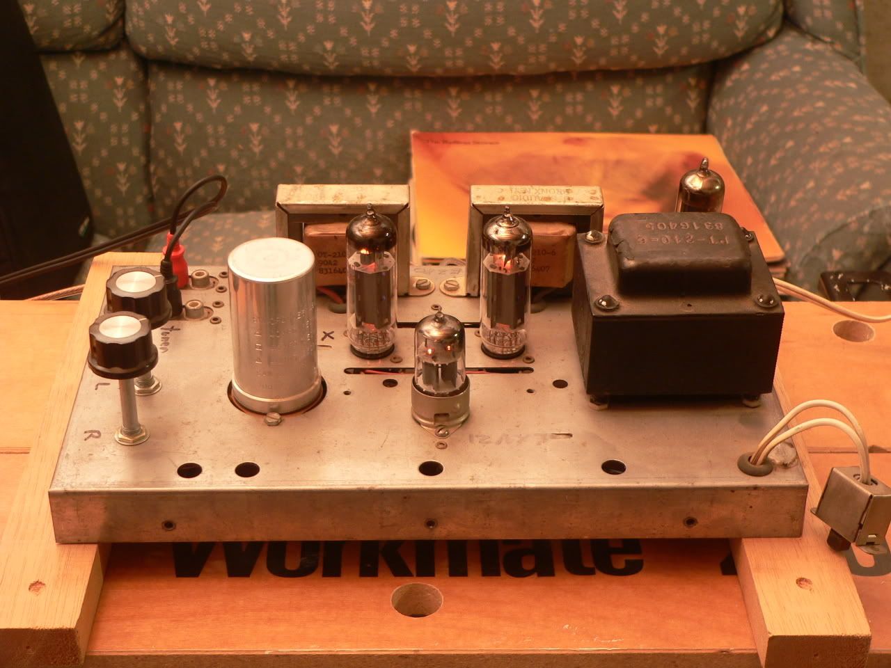
Well, since the only connections nessicary for radio operation are a seperate 6.3v heater supply, B+ and balance controll ( I mounted it on the back of the amp anyway) I was able to remove everything that powered the radio. I will probably build my own psu for the radio some time so that I can put the amp back in if I want.
For now its staying out though! Here is what I have done so far: I replaced the input caps with some .022uf orange drops I had laying around. I also added the 100 uf cap across the cathode resistor. I don't know if the can cap is bad or not, but I think I am going to disconnect it because it is probably not very good quality anyways.
About the strange fb network.... It seems to me that while it is connected to b+2, you will notice that thats the power for the screens. Maybe we have some sort of grid feedback here?
Anyways, any sugguestions on how I should go about modifying this? Should I add a pot in the network to change the feedback amount?
BTW, with the exception of power x-frmr ohm readings the sams was dead on.
Here is the Sams for this amp! Mind you mine does not have the tone controlls on the amp , rather in the radio, but they are the same.
http://getchellaudio.googlepages.com/magnavox.jpg
I removed them here:
Your right about the 150k resistor. I got to thinking about that the other day before I re-read your post. I thought it would make sence to have any background hum be injected in the fb network and canceled. Sly trick there! I wonder what the condition of my multi-cap is then? The amp works fine and has a very low noise floor, and there is no hum/hiss at all, even with my ears up against my 98db speakers!
http://getchellaudio.googlepages.com/magnavox.jpg
I removed them here:
An externally hosted image should be here but it was not working when we last tested it.
Your right about the 150k resistor. I got to thinking about that the other day before I re-read your post. I thought it would make sence to have any background hum be injected in the fb network and canceled. Sly trick there! I wonder what the condition of my multi-cap is then? The amp works fine and has a very low noise floor, and there is no hum/hiss at all, even with my ears up against my 98db speakers!
I went through and redid the amplifier. I left it mostly stock, changing out some old wiring and capacitors. I found one of the 150k resistors was either out of tolerance or had been replaced, however no evidence of it being replaced could be found. It was differnet looking ( grainy on the outside) and a different value , 390k. I also found that the two input caps differed in brands,and the two cathode bypass caps differed in brand too.
anyways I replaced the coupling caps with .01uf 400v metal film caps from radio shack, and the input caps to .1uf 250v ones. I added a 100uf cap across the cathodes, and I plan on seperating them soon with 200r on each.
I got rid of the 33k/.047 frequency shaping network in the feedback also, which helped a little with the low end. However the amp still seems to lack some low end, certain songs it is there, but others it needs a lot of boost to bring it up. Poor OPT's in the bass dept or something else?
I will post a pic asap, I have to wait for the poly on the base to finish drying before I can put it back on the amp. It really cleaned up nicley for a $50 amp 😀
ThSpeakerDude88 said:However the amp still seems to lack some low end, certain songs it is there, but others it needs a lot of boost to bring it up. Poor OPT's in the bass dept or something else?
The device this is out of was never intended to get below 100 Hz, so unless you go parafeed, you won't extract much bass. Note: a parafeed choke will cost as much as new OPTs... time to just consider a scratch build.
Enjoy it for what it is... these also make good mid-tweeter amps (ie use 80 hz or higher only with an active woof)
dave

Poor OPT's in the bass dept or something else?
that should not stop you using the amp on midrange, that's where small power se tube amp excell
try to use them to drive big woofers and they fail
The amp has pretty decent bass as it is, I don't usually turn it up loud enough to clip it, as far as power limits go, when I want to do that I use my solid state receiver. I am thinking about gutting my x-overs and tri-amping the speakers ( or at least bi-amping). My modified ST35 clone will be completed soon so I would be able to use it to drive the woofers.
I really love the sound of this amp, I have another one coming from ebay. I liked the radio it was out of, so I am going to use the parts from the two to restore a good working one.
TY I like your amp, it looks like you have some heaftier output iron than I have. How warm does your power tranny get? I noticed mine gets pretty hot after a while. Maybe I should try a power resistor in line with the AC power to drop the voltage a bit so I'm not hitting the 117v x-frmr with 124v?
How large would the chokes have to be...would they possibly fit under thr chassis? I am open to the idea if it won't break the bank- it would be neat to experiment. This is actually a pretty fun and easy amp to modify.
Thanks. Looking at the eBay photos, I don't think my OPTs are any larger. It's probably just the angle in my picture. Mine started out its life with some bass and treble controls, which were gutted after I took ownership. It's a nice little amp, but tends to run the output tubes just a hair too hard. There's a thread around here somewhere about it.
Most all of my power transformers get hot. I'd say anything under 125 deg F is unusually cool for a tube amp PT. I've learned not to worry too much as long as I can keep a finger on the top for at least one or two seconds.
Yes, today's line voltage isn't what it used to be. I've got similar problems with some of my old gear. There doesn't seem to be a clear and easy fix. Maybe try installing a NTC like the CL-90 in series with the power cord? It'll drop a volt or two, and give you a little bit of a soft start for the rectifier.
Ty_Bower said:<snip>
Yes, today's line voltage isn't what it used to be. I've got similar problems with some of my old gear. There doesn't seem to be a clear and easy fix. Maybe try installing a NTC like the CL-90 in series with the power cord? It'll drop a volt or two, and give you a little bit of a soft start for the rectifier.
Just mount a small filament transformer in a suitable metal box with a receptacle and wire it to buck the line voltage. A 2 - 3A 6.3V to 8V unit will do the job nicely. For safety put a fuse in series with the whole mess at the input end and fuse about 75% of the transformer's rated capacity. Ground the case.
Wire the primary in parallel with the incoming AC, wire the secondary in series with the load. Reverse one winding if it boosts instead of bucks, or use a dpdt toggle switch to allow you to do either if needed.
Use a decent transformer and this will be mechanically much quieter than the typical variac.
Thanks for the advice... I don't have a variac but your idea sounds good. I have a few old radios designed to run off of 110-117v so it would be nice to have a little sort of "Power conditioner for tube amps."
I think I can get a little 6.3v x-frmr @ radio shack. I know you said that it needs to be 2-3 amps...if I am going to be powering more things with this do I basically get the same wattage that the unit will draw, or just the amount of wattage needed to drop the voltage by 6v?
I think I can get a little 6.3v x-frmr @ radio shack. I know you said that it needs to be 2-3 amps...if I am going to be powering more things with this do I basically get the same wattage that the unit will draw, or just the amount of wattage needed to drop the voltage by 6v?
Transformer needs a minimum current rating about 25% - 30% higher than the highest load current you need to run the device connected to it. (This is to prevent overheating.) More can't hurt.
So if your radio uses 100W this equates to about 0.85A so in this instance I would use something larger than a 1A transformer - say 1.5A - 2A to be safe. (Devices with bridge rectifiers, half wave ss or tube rectification and/or lots of capacitance it would be a wise idea to double the rating to account for the device's power factor.)
So if your radio uses 100W this equates to about 0.85A so in this instance I would use something larger than a 1A transformer - say 1.5A - 2A to be safe. (Devices with bridge rectifiers, half wave ss or tube rectification and/or lots of capacitance it would be a wise idea to double the rating to account for the device's power factor.)
hey I just thought of something...I've got an extra 6.3v winding doing nothing inside the amp... It was only used to run the radio.
Could I utilize that to drop my line voltage? If so does it have to be wired in any particular phase to not effect the other windings?
The whole radio consumed about 90 watts, so I assume that the amp its self is drawing about 40 or so watts, so the heater winding would definatly have enough current capability. However if I did this would it still run hot, or would it have no effect on the transformer other than bucking the voltage down to the proper level?
ThSpeakerDude88 said:hey I just thought of something...I've got an extra 6.3v winding doing nothing inside the amp... It was only used to run the radio.
Could I utilize that to drop my line voltage? If so does it have to be wired in any particular phase to not effect the other windings?
The whole radio consumed about 90 watts, so I assume that the amp its self is drawing about 40 or so watts, so the heater winding would definatly have enough current capability. However if I did this would it still run hot, or would it have no effect on the transformer other than bucking the voltage down to the proper level?
For safety reasons I wouldn't do this although it would work at least short term. The problem is two fold, the rating of the 6.3V winding is important, and I am concerned about insulation break down in that secondary winding, it probably was not designed to stand off line voltage. Transformer construction on the primary side usually includes some means to assure that if the primary winding insulation fails AC line voltage doesn't end up on the chassis. (Note that in older transformers this unfortunately sometimes isn't the case.) Insulation failures on the secondary side may let out smoke, but normally would not constitute an electrocution hazard to the user, doing what you propose might significantly increase that risk.
You should add a 3 wire line cord and ground the chassis to make it safe if you choose to do this. Check the filament voltages afterwards to make sure that you phased the winding correctly - they should drop by roughly 5%.
I see what you mean, and now that I think about it, it might be safe for a new transformer but your right about the old one's insulation being old and easier to break down. I think I will just use a seperate 6.3v transformer.
I do know that it has seperate widings for the two heater taps, there is no continuity between them.
By the way, I just got my other radio in the mail. Its in bad shape but I can use the cabinate for a display case like I wanted.
How come these little amps differ from radio to radio? This is the same exact model, yet it has a seperate connector for the balance controll instead of it being on the main connector. Also, the can cap is different, and seems to have failed as someone has recently added a 47uf cap to the psu. They also replaced the power cord. I have not tried to power it up yet because I want to make sure they didn't change anything else.
The one I have has Mullard 6bq5's which were branded magnavox, yet the new one has Magnavox branded Japanese 6bq5's. I did score an RCA 6EU7 in it, but I don't know if it is a usa made or Mullard. Also, the 6CA4 is labled motorola. RCA maybe?
ThSpeakerDude88 said:I see what you mean, and now that I think about it, it might be safe for a new transformer but your right about the old one's insulation being old and easier to break down. I think I will just use a seperate 6.3v transformer.
I do know that it has seperate widings for the two heater taps, there is no continuity between them.
By the way, I just got my other radio in the mail. Its in bad shape but I can use the cabinate for a display case like I wanted.
How come these little amps differ from radio to radio? This is the same exact model, yet it has a seperate connector for the balance controll instead of it being on the main connector. Also, the can cap is different, and seems to have failed as someone has recently added a 47uf cap to the psu. They also replaced the power cord. I have not tried to power it up yet because I want to make sure they didn't change anything else.
The one I have has Mullard 6bq5's which were branded magnavox, yet the new one has Magnavox branded Japanese 6bq5's. I did score an RCA 6EU7 in it, but I don't know if it is a usa made or Mullard. Also, the 6CA4 is labled motorola. RCA maybe?
Running changes were common to cost reduce the product, (two connectors changed to one for example) and to deal with sourcing issues, etc. Magnavox would certainly have bought from the vendor offering the best overall deal at any given time.
- Status
- Not open for further replies.
- Home
- Amplifiers
- Tubes / Valves
- magnavox tube radio