In all probability yes. I suggest you study several datasheets for the recommended value.
This one is close to your operating point on sheet 7.:
EI datasheet
Also be aware that the same level of feedback will not be necessary. The 5K primary OPT will not be optimum (3.5K is recommended by Ei) but will work with less power out.
This one is close to your operating point on sheet 7.:
EI datasheet
Also be aware that the same level of feedback will not be necessary. The 5K primary OPT will not be optimum (3.5K is recommended by Ei) but will work with less power out.
Go ahead, try Triode wired mode.
If you use a Pentode / Triode Wired switch . . . Be Careful! You, and everybody else must Not operate the switch when the amp is powered up (Ouch!).
Just use a 100 Ohm resistor from the screen to the plate for triode operation (or no resistor at all is usually OK).
Use the same cathode resistor.
The cathode current will be very slightly higher, because the screen voltage is slightly higher.
Measure the cathode voltage across the resistor. I = V/R
The open loop gain will be lower in triode mode, than in pentode mode.
That means the negative feedback value will be lower, but that is OK because the triode wired mode has a lower plate impedance, rp. (a good damping factor).
3.5k may give more power.
5K will give lower distortion, and will have higher damping factor.
(do not worry that much about the output transformer primary impedance, your typical "8 Ohm" loudspeaker has impedance that varies with frequencies from perhaps as high as 25 Ohms, and as low as 6 Ohms (or even more impedance variation).
The maximum output power is lower in Triode wired mode.
But try both, listen to both, Have Fun!
The schematic shows a 6BQ5; originally 6BQ5's were Beam Power tubes.
The EL84 was originally a Pentode.
There were patent issues that caused the two designs to be created; but the specifications and curves were essentially the same.
Then, years later, marketing/sales took advantage of the similarity to get more sales, many of those tubes are marked 6BQ5 / EL84, or EL84 / 6BQ5.
Last edited:

I built this one. Love it!. Maybe 1,5 to 2 watts? Enough to fill my livingroom with music. I am using Klipsch RP-160M or some DIY open baffle

Here is
.jpg")
 my livingroom... The green thing is the El 84 Se triode wired...
my livingroom... The green thing is the El 84 Se triode wired...
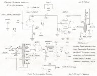
I've built that exact amp, using an 8604 chassis pulled from a Maggie console, the cheap OTs from AES, a 6N2P driver, and 6P14P-EV power tubes. It's been driving my home office audio for a year or two now. It sounds amazing. Note the interesting combination of fixed and cathode bias on the driver - that's from the original Magnavox circuit.
If you can safely do that, measure the plate current of the EL84 with the amp in its current state. Select a cathode resistor to get the same current in the new setup. Keep plate dissipation well below the 11 watt maximum specified for the tube. No red-plating, now!My next project is going to be the attached version of the Magnavox EL84 amp but I'd like to try it first in triode mode. Would it be necessary to change the value of the cathode resistors in the EL84?
The 150k resistor from B+ to the cathode of the driver forms a voltage divider with the cathode resistor, providing additional bias voltage on the cathode (above what an 820R self-bias resistor would provide on its own).
There was a long discussion of this aspect of the circuit in DG's original thread.
There was a long discussion of this aspect of the circuit in DG's original thread.
deafen,
You are absolutely correct.
I missed that: 150k, 820 Ohms, & 10k form a fixed DC bias circuit there.
If you take away the 10k negative feedback resistor, then Both the combination of self bias circuit and fixed bias changes.
By the way, with the right resistor selection, the global negative feedback can be disconnected, and replaced by:
A resistor from the plate of the 6BQ5 / EL84, to the 12AX7 cathode circuit, is also a combination of self bias and fixed bias for the 12AX7.
Why do it that way?
The negative feedback loop's Only low frequency pole is the output transformer primary (Well admittedly, the output tubes cathode self bias circuit bypass cap is also a low frequency pole). But the output tube's cathode low frequency pole (2nd low frequency pole) can be eliminated by using fixed grid bias on the output tube.
A possible disadvantage of Schade negative feedback is the usual RC coupling from the driver plate to the output tube grid.
That low frequency pole is within the negative feedback loop. So both the RC coupling, and the output transformers primary are low frequency poles within the feedback loop (and again the output tubes cathode bypass capacitor is another low frequency pole). Fixed grid bias on the output tube can eliminate that 3rd low frequency pole.
Tradeoffs, and personal decisions.
Can you provide a link to DG's original thread discussion?
Thanks!
Last edited:
Just received Maggie OFMO26 Table top stereo (circa 1963) with this 860x amp. Not sure how to tell diff from 8601, 02, 03, 04. Sams covers all 4 models.I've built that exact amp, using an 8604 chassis pulled from a Maggie console, the cheap OTs from AES, a 6N2P driver, and 6P14P-EV power tubes. It's been driving my home office audio for a year or two now. It sounds amazing. Note the interesting combination of fixed and cathode bias on the driver - that's from the original Magnavox circuit.
Found schema online antique radio forum:
https://img.photobucket.com/albums/v226/GOYA_551st/8601_MagAmp_Without_EQ.jpg
Kinda small. I saved the image and opened in Paint, the magnified to 150%. Not the best :<(
Very similar to Dave's design. One thing I'm changing right away is replacing the 100 ohm 2 w resistor in B+ filter to choke. Also wary of the .01uF discs for audio couplers between stages. First stage.. well maybe- but between driver and final? Nope. Glad to see Dave agrees and uses .1uF
Jim
Last edited:
Sure, you bet! Warning, it's very, very long.Can you provide a link to DG's original thread discussion?
http://www.audiokarma.org/forums/in...ore-out-of-the-8600-series-a-lot-more.665735/
- Home
- Amplifiers
- Tubes / Valves
- Magnavox EL-84 SE, in Triode Mode