Just asking,
Does anyone know what type of Output transformers were used on the Magnavox 6V6 PP stereo and something of equal quality available now?
(Yes I know its a Cliché "Quality" I'm thinking about the feel/sound if you know what I mean)
I'm assuming they were something like Stancore but its just a guess and what actual primary impedance that was used on the amps.
And can anyone post the original schematic if they have a copy..thank's.
I have had a look on the net but its a bit variable..
This is the best I have managed to find, however I'm wondering how many versions were made and which was the best version.
The reason is I have found four black glass 6V6 in a box in the shed. (New unused)
Then I saw this on youtube and the dewey eyes started..LMAO I even have a copper plate..
https://www.google.co.uk/search?q=magnavox+copper+utube&biw=1280&bih=585&source=lnms&tbm=isch&sa=X&ved=0CAgQ_AUoA2oVChMI4-zv_KXkxgIVQa8UCh3JsQ0X#imgrc=7fldHH6B1gYZYM%3A
Just thinking about AB resistors with some kind of treatment or encapsulation and Jupiter reds or copper/wax caps.
Regards
M. Gregg
Does anyone know what type of Output transformers were used on the Magnavox 6V6 PP stereo and something of equal quality available now?
(Yes I know its a Cliché "Quality" I'm thinking about the feel/sound if you know what I mean)
I'm assuming they were something like Stancore but its just a guess and what actual primary impedance that was used on the amps.
And can anyone post the original schematic if they have a copy..thank's.
I have had a look on the net but its a bit variable..
This is the best I have managed to find, however I'm wondering how many versions were made and which was the best version.
The reason is I have found four black glass 6V6 in a box in the shed.
(New unused)Then I saw this on youtube and the dewey eyes started..LMAO I even have a copper plate..
https://www.google.co.uk/search?q=magnavox+copper+utube&biw=1280&bih=585&source=lnms&tbm=isch&sa=X&ved=0CAgQ_AUoA2oVChMI4-zv_KXkxgIVQa8UCh3JsQ0X#imgrc=7fldHH6B1gYZYM%3A
Just thinking about AB resistors with some kind of treatment or encapsulation and Jupiter reds or copper/wax caps.
Regards
M. Gregg
Attachments
Last edited:
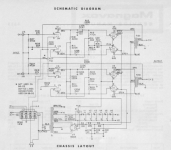
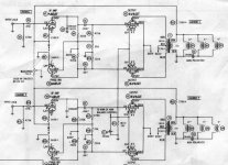
Is this what you are looking for?
OPT PRI impedance is 150 ohms according to the schematic found. Maybe using EI-57 lamination core.
OPT PRI impedance is 150 ohms according to the schematic found. Maybe using EI-57 lamination core.
Attachments
Last edited:
Is this what you are looking for?
OPT PRI impedance is 150 ohms according to the schematic found.
Hi thank you for posting,
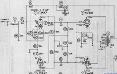
Is the schematic Magnavox? The layout looks very similar..6EU7>>>12AX7?
Cathode 6V6 180>>125 ohm..B+ voltage could be different?
Regards
M. Gregg
Last edited:
Hi thank you for posting,
Is the schematic Magnavox? The layout looks very similar..6EU7>>>12AX7?
Regards
M. Gregg
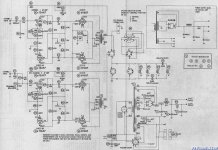
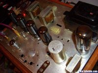
Yes I think it is, as both photo and schematic are posted byningokc
the schematic maybe original but many parts in amp photo are replacements, OPT could be original.
There was a discution on elforum.ro this year.
A friend of mine LMOlimpiu reparired a magnavox93. Here is the link: Scheme amplificatoare pe tuburi&linkuri - Pagin? 14 - Audio pe tuburi - Forumul Electronistilor
A friend of mine LMOlimpiu reparired a magnavox93. Here is the link: Scheme amplificatoare pe tuburi&linkuri - Pagin? 14 - Audio pe tuburi - Forumul Electronistilor
Attachments
That's interesting and a bit strange,
The output Tx windings are not balanced and C5 and C6 are different.
Your first post of between 130-150 ohms looks about right..
Time to have a think..
Perhaps with AB resistors a slow bake then seal the ends with slow drying epoxy then paint the whole thing with a sealant.
Regards
M. Gregg
The output Tx windings are not balanced and C5 and C6 are different.
Your first post of between 130-150 ohms looks about right..
Time to have a think..
Perhaps with AB resistors a slow bake then seal the ends with slow drying epoxy then paint the whole thing with a sealant.
Regards
M. Gregg
Last edited:
The 150 ohms is most likely the DCR of the primary. The primary Z is more in the neighborhood of about 7-8k. The lower the impedance the more power but also more distortion.
This is why I was wondering about the actual value used because most of the drawings seem to give this value which doesn't make much sense..
2nd table down..
http://www.hammondmfg.com/1608.htm
Regards
M. Gregg
Last edited:
That's interesting and a bit strange,
The output Tx windings are not balanced and C5 and C6 are different.
Your first post of between 130-150 ohms looks about right..
Time to have a think..
Perhaps with AB resistors a slow bake then seal the ends with slow drying epoxy then paint the whole thing with a sealant.
Regards
M. Gregg
"The two different coupling caps values relate partly to the paraphase splitter..."
Yes like other already pointed out it is DCR PRI/SEC = 150/0.3, so low they can not be actual Z, which is 7-10K for Pentode mode. The DCR for pri is likely not bifilar so are copper resistance difference between the 2 windings.
Why are you using DCR to calculate the turns or impedance ratio? The 175's OPT is rated for 6k:4~6. The coupling capacitor have different values because the NFB is applied to only one half of the input/PI pair.
The question is what is the actual value of the Magnavox O/P Tx primary some people seem to have used 8K..with 6V6.
The Circuit diagrams all have F/B however the Caps are the same value on one diagram and different values C5/C6 on the other.
Regards
M. Gregg
I gave you the spec for Amp-175, don't know about the others. If you have a chassis number, that would make things easier to look up. Again, depending on the model and what kind of NFB was used, Magnavox used different coupling capacitors.
This is a from scratch build.
Not a restore..
Regards
M. Gregg
The two different coupling cap sizes may have been to introduce some 2nd harmonic distortion at the bass end, to cover up the poor LF response of the tiny OTs. Fake bass.
If you are building from scratch, get some real OTs.
That's probably what will happen..
It starts as a look see then gets modified..
Perhaps something like 15 watt 8K 8ohm Edcor's
However what is the ideal Magnavox circuit?
Something like 6sl7's driving 6L6's..some think the 6V6 is better..
I don't want to go the EL route..
Regards
M. Gregg
- Status
- This old topic is closed. If you want to reopen this topic, contact a moderator using the "Report Post" button.
- Home
- Amplifiers
- Tubes / Valves
- Magnavox 6V6 circuit and output transformers.