
Hi,
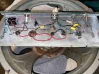
Does this look correct? Additionally, I was going to run the ground wire from the wall plug to the frame of transformer and from the frame of the transformer, to the plug on the chassis. Thanks
Edit: It doesn't seem right because there is power at the transformer all the time.
Does this look correct? Additionally, I was going to run the ground wire from the wall plug to the frame of transformer and from the frame of the transformer, to the plug on the chassis. Thanks
Edit: It doesn't seem right because there is power at the transformer all the time.
Attachments
Last edited:
I'm not going to wire it like that. I've removed the fuse from there. I'm going to interrupt the power cord and primaries with a switch and put the fuse before the transformer. It might be out of form to have 2 switches, but I don't want power to the transformer all the time.
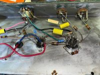
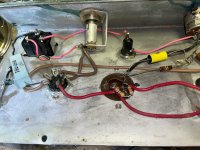
I located the correct schematic. There is static when the tubes warm up after several seconds that gets louder with the volume control. It plays music at a decent volume. The multisection capacitor was changed with a new 50/50 500V because I thought my NOS might be faulty. Tested the tubes. Tried different tubes. When I poke around the capacitors near the 12AX7 and the .01uF, the static diminishes some. The power cables I used are not brand new and the connector on the chassis is from a computer power supply. I have something wired up wrong. Thanks for your help.
P.S. This amp had a shorted power cable and would blow the fuse in my house when plugged in. It worked for a few years prior to that.

P.S. This amp had a shorted power cable and would blow the fuse in my house when plugged in. It worked for a few years prior to that.
The 35W4 is a half-wave rectifier, so the full DC current flows through the isolation transformer secondary, Transformers don't like DC current through a winding, they tend to saturate which leads to excessive current draw and overheating. It only "works" because the isotrans is rated for some 20 times the actual current; a different transformer may or may not overheat or blow fuses.
I would not call this "safe."
Better to disconnect the 35W4 plate and substitute a silicon diode bridge. And use a 3-wire line cord so you can ground the chassis and power supply negative to the safety ground. (Keep the filament connected to maintain the heater string voltages).
I would not call this "safe."
Better to disconnect the 35W4 plate and substitute a silicon diode bridge. And use a 3-wire line cord so you can ground the chassis and power supply negative to the safety ground. (Keep the filament connected to maintain the heater string voltages).
It doesn't overheat or blow fuses. It did before, It actually tripped the circuit breaker, I tried to edit it too late. The old power cord was shorted.
N-77U
Electrical Specifications (@25°C)
1. Maximum Power: 100 VA
2. Input Voltage: Series: 230VAC, 50/60Hz; Parallel: 115V, 50/60Hz
3. Output Voltage: 115V @ Full Secondary Load: 0.86Amps RMS
5. Voltage Regulation: 9% TYP @ full load to no load
N-77U
Electrical Specifications (@25°C)
1. Maximum Power: 100 VA
2. Input Voltage: Series: 230VAC, 50/60Hz; Parallel: 115V, 50/60Hz
3. Output Voltage: 115V @ Full Secondary Load: 0.86Amps RMS
5. Voltage Regulation: 9% TYP @ full load to no load
Last edited:
- Home
- Live Sound
- Instruments and Amps
- Magnatone Starlet Model 107. How to make it safe?