Hi, again,
Well, waiting for parts for my last repair, I'll start with this one, it has reached me yesterday.
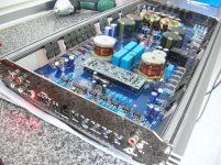
When connected, no sound, no voltage at the speaker output, the relay is not active, and no rail voltage ... only protection led on.
I have reviewed the most common pieces, finding results, mosfet output, all right, power mosfet too, well ...
I have also reviewed some tensions, which have seemed to me little ... I do not know ....
Any idea?
Well, waiting for parts for my last repair, I'll start with this one, it has reached me yesterday.
When connected, no sound, no voltage at the speaker output, the relay is not active, and no rail voltage ... only protection led on.
I have reviewed the most common pieces, finding results, mosfet output, all right, power mosfet too, well ...
I have also reviewed some tensions, which have seemed to me little ... I do not know ....
Any idea?
Attachments
Check all of the 470 ohm resistors (generally marked 4700) on the driver board. Also check all of the small SMD transistors near those 470 ohm resistors. Check for leakage as well as checking for open junctions.
On all of the components near the ends of the driver boards, check for bad solder connections.
On all of the components near the ends of the driver boards, check for bad solder connections.
Well, first, thanks for your reply, Perry.
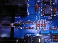
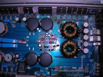
I have checked all the resistances that you have told me, and well, also all drivers and smaller transistors smd, I removed the motherboard, I've seen from behind, and I watched closely all welds without finding fault, I have only seen in the protection circuit an electrolytic capacitor, a little swollen, (see picture one) but nothing more ...
A couple of hours, the same guy who brought me this amp, I've brought another well, for pieces done, because it is in worse condition, (see photo two), I say this, as it helps for something, Perry .
Attachments
Did you try installing the driver board from the second amp into the first amp to see if it would power up normally?
Well, I made the change, card drivers, of the amplifier 2 to the amplifier 1, but no luck, still the same, there has been no change, nothing works, nothing is heated, only led, lit red protection, and ... nothing more ....
Weird?? ...
Weird?? ...
Try repairing the second amp. If you can get it working and can confirm that both driver boards are OK, that will help narrow down the possible problems on the first amp.
mmmmhhmm .... yes, buttt ... is that I have some of the pieces in my closet ...
For example: I have several units IRF640 and 9640, also I have eight units of IRF3205, could they be substitutes of IRFZ48N, which are originally mounted amplifier?
For example: I have several units IRF640 and 9640, also I have eight units of IRF3205, could they be substitutes of IRFZ48N, which are originally mounted amplifier?
I assumed that the power supply FETs in amp 1 were OK and you could move them from one amp to the other.
If you want to order parts and parts are easy to get, do so. Often, in the EU, parts take a long time to get.
If you want to order parts and parts are easy to get, do so. Often, in the EU, parts take a long time to get.
Yes, that's right, Perry, one of the amplifiers, has the mosfet power supply in good condition, as are the output MOSFET, which are good too,,,
But, is that it seems that I do not like that idea,,, I hope you understand me, Perry, I like to replace them with new ones, I do not know, it seems more reliable ...
Anyway, I almost always ask a mouser parts in germany, and it takes a week is not long, right?
But, is that it seems that I do not like that idea,,, I hope you understand me, Perry, I like to replace them with new ones, I do not know, it seems more reliable ...
Anyway, I almost always ask a mouser parts in germany, and it takes a week is not long, right?
The suggestion was to allow you to find all of the defective components and place only one order.
There was no suggestion that you install used parts for the final repair.
There was no suggestion that you install used parts for the final repair.
I keep waiting for me to reach the parts that I ordered.
Perry, I thought, that before changing the 29 components of the amplifier 1 to the amplifier 2, (not because they want to, forgive me, I do not want you to bother ) I checked the voltages at the IC, TL494C and TL072, and are as follows:
TL494
pin 1: 0,015
pin 2: 4,91
Pin 3: 4,78
pin 4: 3,34
pin 5: 1,4
pin 6: 3,4
pin 7: 0
Pin 8: 12,47
pin 9: 0
pin 10: 0
pin 11: 12,47
pin 12: 11,66
pin 13: 5,0
pin 14: 5,0
pin 15: 5,0
Pin 16: 8,55
TL072
pin 1: 1,30
pin 2: 5,01
Pin 3: 1,06
pin 4: 0
pin 5: 6,25
pin 6 1,9
pin 7: 9,29
Pin 8: 11,68
What do you think you of these measures?
If these values are correct, I will begin to change the components of an amplifier, the other.
Something is driving pin 7 of the TL072 high. It's likely the voltage on pin 5. You could try grounding that pin (to pin 4 of the same IC) to force the amp on. If the amp comes on, the protection circuit would be defeated so you'd have to have all transistors clamped down and a limiter or small fuse in the B+ line to protect the components clamped to the heatsink.
You mean, to make a bridge between pin 4 and pin 5?
And, to turn the amplifier, can I put in B+line 10 amp fuse, or should be less?
And, to turn the amplifier, can I put in B+line 10 amp fuse, or should be less?
Yes, solder a bridge between 4 and 5.
A 10 amp fuse may be enough. Nothing larger than a 15A.
Clamp all transistors.
A 10 amp fuse may be enough. Nothing larger than a 15A.
Clamp all transistors.
- Status
- Not open for further replies.
- Home
- General Interest
- Car Audio
- MACROM M1A.1500D led protection, on.