Can anyone help me figure this amp out? So a friend of mine has had this amp sitting around for 17 years since it stopped working. I know there have been two people before myself that have had this amp open and tried to get it working again. The only thing I can see that has been done is someone has tried repairing a trace that wasn't broken but looked as if it were. I myself have replaced the RCA input and outputs as I noticed they had been broken once before and someone tried soldering the break I replaced it with a new one. Then the switch for the LPF HPF and Full was broken off at the black plastic knob part so got a new one of those on it. The amp powers on and I even have audio coming out of it but without power. I can't find much more than a few pics online of this amp. Owner says he remembers the status light on it being green when it was operating fine led is now red. Both fans kick on immediately upon it switching on, owner couldn't recall wether this was the same under normal working conditions. This amp has 8 irfz44's, 4 tip35c's and 4, 36c's all of which I have pulled from the board and seem to be good according to my meter tested on ohms as well as the diode setting. The amp also has a gl494 I'm guessing is the same as the tl494 I am unsure how this part of the amp would be working under normal conditions I have the readings from all 8 legs while the amp is on at 12.1v and 5 amps. Not sure where to go from here...
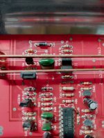
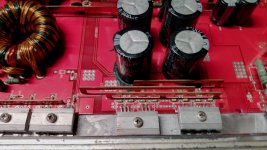
Post a good quality photo (in focus, no flare from the flash...) of the area shown below. Have that area fill the entire frame. Straighten any other component(s) that blocks the view of any other.
Only 8 legs on the 494?
Are you saying that it's drawing a constant 5 amps or that you are powering it with a 5 amp power supply?
Only 8 legs on the 494?
Are you saying that it's drawing a constant 5 amps or that you are powering it with a 5 amp power supply?
My fault. I use macros and hit the wrong button.
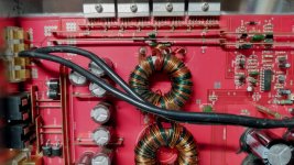
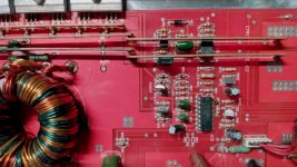
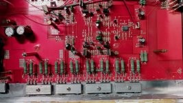
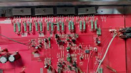
Post a good quality photo of the component side of the entire main board and the component side of any driver boards.
Post a good quality photo of the component side of the entire main board and the component side of any driver boards.
Sorry for the late response, I have been incredibly busy lately. So I have gathered some more information from the owner about the amp. So owner said that when the amp stopped working he had ran inside his house from his car, left car running door open and amp working to come out to his dog (which was a small bread) who was damp from it raining laying on the amp and it was no longer working and was in protect but was still powered on with no blown fuses.
Attachments
-
 IMG_2024-03-21-22-40-30-862.jpg354.1 KB · Views: 68
 -
 IMG_2024-03-21-22-40-44-936.jpg378.1 KB · Views: 63
 -
 IMG_2024-03-21-22-41-28-973.jpg324 KB · Views: 64
 -
 IMG_2024-03-21-22-42-02-478.jpg322.4 KB · Views: 72
 -
 IMG_2024-03-21-22-42-54-130.jpg391.6 KB · Views: 69
 -
 IMG_2024-03-21-22-43-58-539.jpg321.8 KB · Views: 66
 -
 IMG_2024-03-22-00-06-02-589.jpg337.8 KB · Views: 78
 -
0 bytes · Views: 0
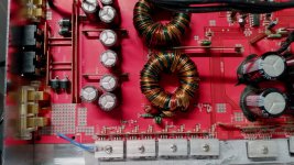
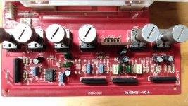
The picture of the board that has the meters on it was taken before I installed the new switch for the pass filter
Copy and paste the following list and fill in the blanks. With the black probe on the amp's ground terminal, post the DCV on each terminal of the 494.
Pin 1:
Pin 2:
Pin 3:
Pin 4:
Pin 5:
Pin 6:
Pin 7:
Pin 8:
Pin 9:
Pin 10:
Pin 11:
Pin 12:
Pin 13:
Pin 14:
Pin 15:
Pin 16:
Pin 1:
Pin 2:
Pin 3:
Pin 4:
Pin 5:
Pin 6:
Pin 7:
Pin 8:
Pin 9:
Pin 10:
Pin 11:
Pin 12:
Pin 13:
Pin 14:
Pin 15:
Pin 16:
Last edited:
Pin 1: 0.89
Pin 2: 8.86
Pin 3: 8.04
Pin 4: 0.88
Pin 5: 3.47
Pin 6: 7.16
Pin 7: 0.00
Pin 8: 12.97
Pin 9: 0.05
Pin 10: 0.07
Pin 11: 12.97
Pin 12: 12.16
Pin 13: 10.24
Pin 14: 10.26
Pin 15: 10.26
Pin 16: 12.97
Pin 2: 8.86
Pin 3: 8.04
Pin 4: 0.88
Pin 5: 3.47
Pin 6: 7.16
Pin 7: 0.00
Pin 8: 12.97
Pin 9: 0.05
Pin 10: 0.07
Pin 11: 12.97
Pin 12: 12.16
Pin 13: 10.24
Pin 14: 10.26
Pin 15: 10.26
Pin 16: 12.97
Ok, I'll get the 494 swapped with a new one thanks for all of your help so far I'll post what happens when I have replaced it with a new one
If the amp has pull-down resistors on the PS FETs, power it up without the IC in the circuit and confirm that there is no significant voltage on those 3 IC pads.
- Home
- General Interest
- Car Audio
- MA Audio HC4002 Class AB amp in protect mode