Your link did not work! a 10k potentiometer will do it. I using this http://www.partsconnexion.com/tkd_73334.html
Would it be ok to change the orientation of the main mosfets? I want to attach them to the heatsink horizontal on the up side of the amp case? Will it affect the sound? I'm trying to make the amp compact which limits the ways I could place the components.
yes u can do this
You absolutely cannot lay a power heatsink flat without forced air (fan) and expect it to cool effectively. Finned heatsinks reguire vertical arrangement for the heated air to rise naturally, flowing unimpeded up the line of the fins, otherwise, the reduction in dissipation can be as much as 80% of the heatsink's design rating.
A class AB bipolar transistor amplifier that has low bias current may work like this, with a crippled heatsink, because dissipation can be low at low power output too. When the amplifier begins to produce its rated power however, it will overheat and fail. Mosfet amplifiers require at least 100mA bias per pair to give lowest distortion, and good sound. The M400 has 2 pair and requires ~200mA min. bias current. That's around 25W watts dissipation each channel. This this will make the specified size heatsink quite warm, even with no signal.
If you only use your amplifier at low power, it may be OK - until in hot conditions you turn it up a bit. Then, the Mosfets will go into thermal limiting or even bye,bye amp! If you must have a flat heatsink, build the case top with thick, 4-6mm sheet aluminium and use the case as a large area heatsink, because you will be wasting your time and money using a wrongly aligned finned heatsink.
You absolutely cannot lay a power heatsink flat without forced air (fan) and expect it to cool effectively. Finned heatsinks reguire vertical arrangement for the heated air to rise naturally, flowing unimpeded up the line of the fins, otherwise, the reduction in dissipation can be as much as 80% of the heatsink's design rating.
A class AB bipolar transistor amplifier that has low bias current may work like this, with a crippled heatsink, because dissipation can be low at low power output too. When the amplifier begins to produce its rated power however, it will overheat and fail. Mosfet amplifiers require at least 100mA bias per pair to give lowest distortion, and good sound. The M400 has 2 pair and requires ~200mA min. bias current. That's around 25W watts dissipation each channel. This this will make the specified size heatsink quite warm, even with no signal.
If you only use your amplifier at low power, it may be OK - until in hot conditions you turn it up a bit. Then, the Mosfets will go into thermal limiting or even bye,bye amp! If you must have a flat heatsink, build the case top with thick, 4-6mm sheet aluminium and use the case as a large area heatsink, because you will be wasting your time and money using a wrongly aligned finned heatsink.
Thank you for your detailed explanation, Ian, you saved me a lot of future headache and melted mosfets. The heatsinks I have are of dimensions which will make a far from compact amp size since they're 20cm high or so (instead of wide and short, this is the only one which the store had in stock). I'm thinking about position them vertically inside a "perforated" case and using a big and very slow fan to circulate air through them.
Last edited:
I hope you plan to obtain the correct size of heatsink to suit your amplifier. We have discussed this previously but I will make a suggestion for size, if you aren't aware or are simply copying the kit PCB without having its specifications.
First, don't be limited by what you can buy locally. The sizes you linked to previously were for low power, perhaps class D chipamps but you have 2 x 200W class AB Mosfet amplifiers to cool, in a warm climate. These make serious heat and those toy heatsinks just won't work, even with fans running fast.
I estimate that each amplifier will require a heatsink of better (less) than approximately 0.5degrees K/Watt). For a 2U rack case heatsink height of ~80mm, that is a heatsink 45 mm deep x 250 wide minimum. You need 2 of those for convection cooling. Here is an illustration of economical local products. The type MF25-75 is probably a good type, bearing in mind that: wide spaced fins (say 10mm pitch) + low and wide sinks are more efficient than tall and narrow forms for convection cooling: http://www.conradheatsinks.com/products/
To use a fan instead, a proper tunnel extrusion with variable speed fan and controller would be the most efficient means and I assume you can buy those or the country would stop running without them. They are commodities used in pro.sound, communications and large computer systems, so they will be available somewhere. The total cooling requirement will be better (less than) 0.25 degrees/watt. If the heatsinks are not rated for their cooling capacity, the seller can't have a clue what he's selling or what it's good for and so , you can't know either. It's also pointless buying little pieces of heatsink and bolting them next to each other, because they don't conduct heat that way. The idea being, to move the heat out to the extremities of the heatsink as fast as possible or it will be inefficient.
Don't buy things because they look right - buy what is specified right or buy a smaller kit amplifier to suit what you can buy.
Last edited:
I hope you plan to obtain the correct size of heatsink to suit your amplifier. We have discussed this previously but I will make a suggestion for size, if you aren't aware or are simply copying the kit PCB without having its specifications.
First, don't be limited by what you can buy locally. The sizes you linked to previously were for low power, perhaps class D chipamps but you have 2 x 200W class AB Mosfet amplifiers to cool, in a warm climate. These make serious heat and those toy heatsinks just won't work, even with fans running fast.
I estimate that each amplifier will require a heatsink of better (less) than approximately 0.5degrees K/Watt). For a 2U rack case heatsink height of ~80mm, that is a heatsink 45 mm deep x 250 wide minimum. You need 2 of those for convection cooling. Here is an illustration of economical local products. The type MF25-75 is probably a good type, bearing in mind that: wide spaced fins (say 10mm pitch) + low and wide sinks are more efficient than tall and narrow forms for convection cooling: Conrad Heatsinks - Products
To use a fan instead, a proper tunnel extrusion with variable speed fan and controller would be the most efficient means and I assume you can buy those or the country would stop running without them. They are commodities used in pro.sound, communications and large computer systems, so they will be available somewhere. The total cooling requirement will be better (less than) 0.25 degrees/watt. If the heatsinks are not rated for their cooling capacity, the seller can't have a clue what he's selling or what it's good for and so , you can't know either. It's also pointless buying little pieces of heatsink and bolting them next to each other, because they don't conduct heat that way. The idea being, to move the heat out to the extremities of the heatsink as fast as possible or it will be inefficient.
Don't buy things because they look right - buy what is specified right or buy a smaller kit amplifier to suit what you can buy.
Thanks for the informative post. The heatsinks I bought cost me around $160 each, I really wouldn't want to throw them away (they were cut to the length I asked them to). They are about 13cm high, 16cm wide, 1cm base thickness. I couldn't find a way to calculate the heat dissipation they'll provide, so I did a rough estimation... What if I'll cut them in two and bolt them and use thermal paste between the pieces? Looks like I'll have to use them in a taller than usual configuration...
An externally hosted image should be here but it was not working when we last tested it.
Last edited:
Using a taller configuration will be better than dividing the heatsink. You do need each parallel device and ideally, each complementary pair to operate at the same temperature by being thermally close-coupled to each other and sharing current equally. 2 of those (one for each channel if stereo) used as they are, should be OK at typical low power used in homes. Don't cut the sinks further if at all possible.
At high power, Lateral Mosfets do share current well, which makes them relatively safe and easy to use but they will operate more efficiently below this high temperature self-limiting state if they share current at low levels too. Unfortunately, the thermal resistance of a join with grease as the transfer medium will be too high to be any use there. It needs to be used only as a gap filler over a relatively broad area, where the extruded or ground mating metal finishes will likely not be perfect nor perfectly flat.
At high power, Lateral Mosfets do share current well, which makes them relatively safe and easy to use but they will operate more efficiently below this high temperature self-limiting state if they share current at low levels too. Unfortunately, the thermal resistance of a join with grease as the transfer medium will be too high to be any use there. It needs to be used only as a gap filler over a relatively broad area, where the extruded or ground mating metal finishes will likely not be perfect nor perfectly flat.
Hello guys, I'm back to this project after a long long pause... there's actually very little work to do but since this is my first serious full build and it's new to me I'm doing it in baby steps.
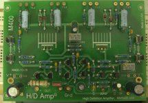
This is a little embarrassing, but could someone who built it know where these parts go on the PCB? The small transistors K1058, J162, and high wattage transistors 2 x c2911, and 2 x a1209 go on slots numbered 9 to 14.
The domain I ordered it from is down(http://www.hdamp.com/M400.html) and I have no documentation for it.
After 3 years I can't wait to hear it...
Thanks for everyone's contribution so far!
You can browse this domain using web.archive.org :
2sk1058 2sk2221 irfp9240 mosfet amplifier schematic
Probably You'll find what You want there.
2sk1058 2sk2221 irfp9240 mosfet amplifier schematic
Probably You'll find what You want there.
You can browse this domain using web.archive.org :
2sk1058 2sk2221 irfp9240 mosfet amplifier schematic
Probably You'll find what You want there.
Thank you for the suggestion! I can see in the photo the mosfet location on the board, T11-T12 are the K1058, T13-T14 are the J162, but I still don't know where the A1209 and C2911 go (T9 and T10 left).
If someone could tell from the parts, I'll try to make a schematic from the parts to "reverse engineer" the circuit.
Another important detail is which transistors must be insulated from their heatsinks?
I wish I could analyze the circuit myself by my knowledge is lacking.
Thank you for the suggestion! I can see in the photo the mosfet location on the board, T11-T12 are the K1058, T13-T14 are the J162, but I still don't know where the A1209 and C2911 go (T9 and T10 left).
If someone could tell from the parts, I'll try to make a schematic from the parts to "reverse engineer" the circuit.
I went over through my pm's and looks like the T11-T14 are to be insulated from the heatsink (for some reason). T9 is the 1209 component, T10 is 2911.
Doing a build with no publicly available documentation has its downsides...
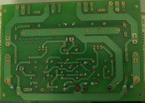
Someone asked me for images of the board. I don't have the part list so if someone has it, please share it as it could help other builders, which is what this community is about:


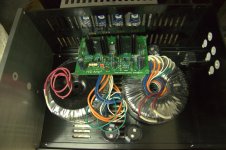
This is roughly the chassis arrangement I'm planning, and it's going to be crowded. Hopefully there'll be no interference due to the short distances between some parts.

This is roughly the chassis arrangement I'm planning, and it's going to be crowded. Hopefully there'll be no interference due to the short distances between some parts.
Attachments
The lack of documentation to this circuit is quite irksome.
Now there's only piece of information required to complete it. Does anybody know which voltages the variable resistors VR1 and VR2 should be tuned for?
Now there's only piece of information required to complete it. Does anybody know which voltages the variable resistors VR1 and VR2 should be tuned for?
Just discovered this a year later .. VR1 is used to set dc offset to zero at the output.
Vr2 is for setting the operating current of the output mosfet , I set it to 20mv across
the big resistor. This board is very well designed, I listened to it every day the last 5 yrs.
With a simple 20k pot, it sounded more alive than my other Yamaha A2100.
Tanaka is a great guy, he still offers technical support - hdamps@gmail.com
cheers
- Status
- Not open for further replies.
- Home
- Amplifiers
- Solid State
- M400 diy kit with 2SK1058/J162 chip