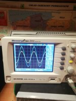
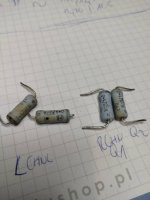
Having a free moment, I tried to check the amplifier with the oscilloscope. I checked the gain, power and frequency characteristics as far as I can operate the oscilloscope and generator.
I did this using dummy load 4 and 8R. Everything looks ok except for a square signal test at 4R. At an amplitude of 8 Vpp, the triangle and sine are at the clipping limit. The square signal causes a squeak inside, the amplifier and speaker protection turns off the output for a while - then there is silence. There is a sequence of protection operation - on / off. I can't see anything specific on the oscilloscope.
I am asking for help and advice or should I worry about it?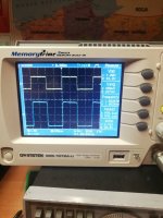
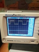


Does the amplifier still work?
The speaker protection kicking in is not a good sign. It means that DC was present in the speaker output.
Square waves are not meant to be used to check maximum output. Square waves are comprised of odd order harmonics (sine waves) that sum to a square. It is a full out clipped sine wave.
Squarewave Testing
Looking at your first oscilloscope shot (was that 8 Ohms?), it looked like you had maxed out your amplifier, drawing very, very high currents. When you did it with a 4 Ohm load, it tried to draw even higher current, probably higher than the amplifier could provide or handle, and that may have caused damage and DC on the output, which triggered the speaker protection.
All I do is my first time so I already have many mistakes behind me. I thought that since sine and triangle do not distort the amplifier at amplitude 8Vpp, so will the rectangle. Hope I didn't destroy anything.
Pictures are with 4R load. Second, when DC protect board is off.
The amplifier sounds normal, but I noticed that under load 4R the bias is different than 8R or without load. It is stable at 0.606V across resistors R13 and R14. I checked for sine, triangle and rectangle and amplitude 5Vpp. With the same amplitude and 4R load, the values are different for different signals and range from 0.537 to 0.652V. Lowering the amplitude stabilizes the bias at 0.6V
Last edited:
It sounds like you got away with torturing your amplifier.😉
Class A push-pull amplifiers can draw more current when pushed:
http://www.firstwatt.com/pdf/art_leave_classa.pdf
Single-ended Class A bias is where a single gain stage operates against some variety
of current source, as compared to push-pull Class A where two complementary stages
operate in opposition to each other. Single-ended Class A is often thought of as the
“king of Class A” by purists because it delivers the lowest order of harmonic distortion,
2nd harmonic, instead of the 3rd harmonic of push-pull.
It also is the least efficient of the Class A configurations, with an efficiency fi gure on the
order of 20%, sometimes less. A limitation of single-ended Class A operation is that the
peak output current is limited to the value of the bias current. By comparison, pushpull Class A can deliver twice the bias current as peak output in Class A, and generally
much more than that in Class AB.
Looking at your oscilloscope shot, the output Vrms=15.9V at 4R, which is 4.0A! P=63W. 😱
...which is, by the way, an outstanding result for an M2x driven by a square wave signal. The transformer and capacitor bank seem good as well, to be able to supply that current with negligible sag dV/dt.
It also goes to show how special these simplistic amplifiers are. M2x is a 0 feedback amplifier as well. Outstanding.
May have to build one.
It also goes to show how special these simplistic amplifiers are. M2x is a 0 feedback amplifier as well. Outstanding.
May have to build one.
You stressed the amp by squarewave signal at its input... anything's possible.
The square waves are usually used at low levels and various frequencies to tune the feedback loop little by-pass capacitors (5pF in Aleph J). Also, you'll be looking for an absence of any HF rubbish superimposed on the squarewave output. The presence of such HF rubbish means instability / HF oscillations.
The trick is to connect the load at the end of the speaker cables; NOT straight at the back of the amplifier; NOT to its binding posts. Also, adding a small cap across the resistor could simulate the crossover caps... Then, you'll be able to tune the feedback cap with a close-to-real load that amplifier will actually see.
I used to play with the above a lot.... a few decades ago... 🙂
8Vpp is a 1W at 8 ohms, how could it be near clipping? What is the diference between 4 and 8 ohms load? That dosn't suond right..
However, there is a problem. Under load 4R, one channel has both sine and triangle signals distorts on the oscilloscope. The second channel cuts the tops asymmetrically. Additionally, the bias floats when adjusting the amplitude. Apart from replacing the 0.47R resistors, I have no idea what to check

Correct me if I'm wrong. Isn't the M2X a balanced design with a bridge output ? In the pic of the first post I see the scope probe ground clipped to one side of the dummy load resistor. If the scope is grounded as it should be, that would certainly trip any speaker protection.
I have installations without grounding (without PE line). The amplifier and oscilloscope are therefore not connected to ground.
I replaced the resistors. This is what the signals on both channels look like. The powers measured at 8 and 4R are 22.8W and 32.6W.
I checked the amplifier with a sine wave from 10hz-100hz at 1Vrms at the input. With a load of 4R I hear the sound of the signal between 5-8khz from the inside of the amplifier (it modulates "quieter-louder" depending on the frequency) . At 8R it is also audible but quieter. The oscilloscope shows nothing special in this range. Should I be worried?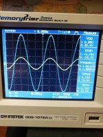
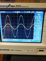


Isn't the M2X a balanced design with a bridge output ?
No, despite the 'X' in its name (often a shorthand for SUSY in Pass Land),
the M2x is not a balanced design.
I have installations without grounding (without PE line). The amplifier and oscilloscope are therefore not connected to ground.
I replaced the resistors. This is what the signals on both channels look like. The powers measured at 8 and 4R are 22.8W and 32.6W.
I checked the amplifier with a sine wave from 10hz-100hz at 1Vrms at the input. With a load of 4R I hear the sound of the signal between 5-8khz from the inside of the amplifier (it modulates "quieter-louder" depending on the frequency) . At 8R it is also audible but quieter. The oscilloscope shows nothing special in this range. Should I be worried?View attachment 909643View attachment 909644
NO, you should stop worrying.
The amp behaves exactly as it should.
You could try to compensate for different gains of output MOSFETs (they are not complementary pair; they have different specs -> check the spec sheets), by carefully tuning the R13 and R14 resistors, but you'll be looking only at one specific parameter - slightly uneven clipping. So, stop worrying.
You could also see if the drive signals are of the same amplitude. For this, you do not have to drive the amp into clipping. Just measure the amplitude of signals at R8 and R9 referenced to the ground at something like few volts of RMS output. Make sure you put the probe away from the gates to prevent oscillations AND the probe is set at 1:10
If you can not stop worrying, build Aleph J which is not a push-pull design.
Last edited:
The output transistor swill sing when stressed the way you are stressing them; you should hear the good old TO3's ... 🙂
@Extreme_Boky
This is my first diy amplifier and first contact with an oscilloscope, that's why I have so many questions. I'm glad that this isn't a cause for concern, so it remains to enjoy the music.
I still have to replace the power supply with more CRC filtering to be able to listen Mountain VIEW without a 100hz buzz and I'm still waiting for the ordered mumetal for edcor.
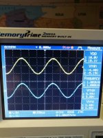
I also checked, as you advised, the signal on r8 and r9. This is what it looks like.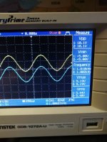


- Home
- Amplifiers
- Pass Labs
- M2X - problem with square signal from generator
