What is the output? is that acoustic SPL? or electrical signal at the amp output.
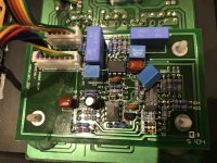
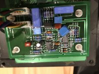
Your description of the bass sounding chopped is typical of a faulty limiter or compressor. The little daughter board mounted on the preamp PC board is the limiter/compressor that M&K added to the circuit. Can you get a picture of the board? Maybe we can figure out the input/output pins and measure the electrical response to confirm if this is where the problem originates.
You might also check on that limiter board to see if there are any electrolytic capacitors. If one of them is being used to hold the peak reference level for determining the limiter setting it could be what is causing the problem.
Last edited:

Hello, that output is acoustic SPL.
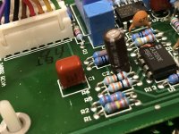
I have attached the pictures of the daughter board, about 3 weeks ago. It measure good With an ESR meter. I have already changed the small electrolytic cap, “C2”, which was a 1micro farad 50v.
I have attached the pictures of the daughter board, about 3 weeks ago. It measure good With an ESR meter. I have already changed the small electrolytic cap, “C2”, which was a 1micro farad 50v.
Attachments
I would be very surprised if it's 20 to 30 Hz response were same as that above that.
It is very expensive, both in resources, materials, design effort, to reach that low with authority, specially if practically NO music program reaches that low.
What for?
Is it doable?
Yes.
Is it a legitimate goal for a commercial, "marketable" subwoofer?
Not so sure about that.
EDIT: I very very very much doubt Elvis recorded anything at all in the 20-30 Hz band.
In fact, old style Bass Amps had little to no output below 80-90Hz or so.
Perceived Bass was all harmonics, little to zero fundamentals.
You are probably listening to vinyl record rumble and poor centering.
That will definitely count as "inconsistent Bass"
Last edited:
Apologies, if you posted pics of the daughter board previously I missed it.Hello, that output is acoustic SPL.
I have attached the pictures of the daughter board, about 3 weeks ago. It measure good With an ESR meter. I have already changed the small electrolytic cap, “C2”, which was a 1micro farad 50v.
You can bypass the limiter board by removing the pins for the green wires from both of the connectors and hook them together.
(The connectors still need to be in place though, to pass supply voltages and ON/OFF signal between pre and power boards)
Reading back thru your posts, it is unclear if your subwoofer always behaved in the manner you describe, or if it is a new development.
The reason I ask, is that your description of "...the first half of A second the sound is louder than after this time." is exactly what you would expect from a limiter with a typical less-than-instantaneous attack time.
You should be able to play a 40Hz tone and slowly turn up the volume. At some loudness level, you should notice that as you continue to turn up the volume the woofer output does not increase.
Try the same thing with the limiter board bypassed. This time you should notice that when you reach that same loudness level, turning up the volume more will result in noticeable distortion. (ie the amp is clipping)
Looking at the parts on the daughter board, the limiter circuit appears to be quite similar to that used by M&K in their older subwoofer lines...not really a surprise I guess.
See the attached schematic for the MX150. You can see the limiter portion of the circuit right in the middle of the schematic, between R96 and R40.
Attachments
Thanks.
The classic CA3080 OTA compressor/limiter application 👍🏻
I would NOT bypass the Factory installed limiter in any case, doubly so in a subwoofer.
You will NOT increase Bass output since it's already reaching physical excursion limits (dangerous) and best case it will become fart-land
.
The classic CA3080 OTA compressor/limiter application 👍🏻
I would NOT bypass the Factory installed limiter in any case, doubly so in a subwoofer.
You will NOT increase Bass output since it's already reaching physical excursion limits (dangerous) and best case it will become fart-land
.
Hmmm...is it possible that it is 15mV AC ripple instead of 15V? If it was 15V you would have a very loud hum coming from the sub even with no input signal applied.
Can you describe your 20-40Hz issue in more detail? Do you have a signal generator where you can input a constant 30Hz tone and slowly turn up the volume to see what is happening? I'm wondering if it is an issue with the M&K Limiter/compressor circuit on the daughter board attached to the pre-amp PCB.
I don't have a schematic for the M&K amp, only the Parts Express Amp which has essentially the same power amp circuit. It is the preamp that is different/improved on the M&K.
Thank-you for posting the schematics for this amp. Also your isolation of problem post and picture.
While I have 9.7V & -9.7V on the CONT line, I only have the -67V on R3 regardless of switch position. Looks like I should check back at Q22 and Q23.
Last edited:
I think Q22 is dead. I can see change on its base when switching the amp on and off. The collector has +68 and emitter is at ground. It doesn't change with the switch. I jumpered the emitter and collector and now get +67 on R3 now. I can not clearly make out the part number on it though. It looks like C1815, but no transistor comes up with that on Mouser. I think it is 2SC1815, which does.
Nice troubleshooting 
You are correct on the transistor part number, 2SC1815. I have encountered a few of these amplifiers over the years with this failure. Note that the VCE rating for the 2SC1815 is 50V, so failure is not surprising when it is asked to handle 68V. The design uses 2SC2240 elsewhere in the circuit which are rated at 120V, so perhaps that was the original intent of the designer. When repairing, I usually replaced the failed 2SC1815 with KSC1845 since it has the same pinout orientation and is easier to find than 2SC2240.
You are correct on the transistor part number, 2SC1815. I have encountered a few of these amplifiers over the years with this failure. Note that the VCE rating for the 2SC1815 is 50V, so failure is not surprising when it is asked to handle 68V. The design uses 2SC2240 elsewhere in the circuit which are rated at 120V, so perhaps that was the original intent of the designer. When repairing, I usually replaced the failed 2SC1815 with KSC1845 since it has the same pinout orientation and is easier to find than 2SC2240.
Last edited:
Thank-you. Its a struggle refreshing old memory cells, working thru it. I did notice that in the specs, but hadn't tried to look up a replacement. I'm preety sure I have some KSC1845's in my Adcom parts bin. Thx.
I am also working on a similar Apex Jr MegaBass plate amp. There are a few differences on the amp board vs the PE version. R3 is 22K on PE, 100K on MB. There is a resistor, cap, and wires soldered to the backside, and not on the PE one.
The problem on the MegaBass is somewhere on the PRE board which is stamped M&K. The MX150 schematic posted in this thread does not match though. 🙁 So its slow going tracing things out and my old eyes reading surface mount parts.
- Home
- Loudspeakers
- Subwoofers
- M&K 12" sealed subwoofer Plate Amp Repair?