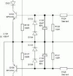
And the negative leg would be marked on lyte cannistor with thick line or arrows or both...or?
I havent looked but I suppose the amp board is marked correctly, so nothing dangerous there
I havent looked but I suppose the amp board is marked correctly, so nothing dangerous there
I am very sorry, I didn't want to start a controversy, but I still see those capacitors (C105 / C106) connected "upside down"
Here is the pertinent portion of the circuit that lesherons posted in the first page of this thread, located at:
http://www.audio-circuit.dk/images/...203 Schem.pdf
C 110 also seem to "look down" but it sees zero volt, so I think there is no problem. It only looks weird...
Here is the pertinent portion of the circuit that lesherons posted in the first page of this thread, located at:
http://www.audio-circuit.dk/images/...203 Schem.pdf
C 110 also seem to "look down" but it sees zero volt, so I think there is no problem. It only looks weird...
Attachments
Hi.
I'm going to making this amplifire.
But there is no any MJL21194 and MJL21193 in my country.
Can I use 2SC5200 and 2SA1943 instead of recommended transistors?
so what do you recommend instead of that transistor?
thanks
I'm going to making this amplifire.
But there is no any MJL21194 and MJL21193 in my country.
Can I use 2SC5200 and 2SA1943 instead of recommended transistors?
so what do you recommend instead of that transistor?
thanks
Boards availability
Hi,
If it is possible to get boards for this project I would be interested. Please pm or send me a message. Thanks.
Hi,
If it is possible to get boards for this project I would be interested. Please pm or send me a message. Thanks.
Regarding the BOM do you need for the emiter resistor 5 watt types but can I use 3 watters aswell?
Lynx PCB v.3
I`m planning to do a new Subamp for my A.P Rhea.
Originally it has an amp with 300W at 4ohm (2 x 8 ohm elements driven)
Will this amplifier meet my needs?
What power and filter circuit is recommended for use together with this amplifier
in such case?
regards,
ManU
I`m planning to do a new Subamp for my A.P Rhea.
Originally it has an amp with 300W at 4ohm (2 x 8 ohm elements driven)
Will this amplifier meet my needs?
What power and filter circuit is recommended for use together with this amplifier
in such case?
regards,
ManU
Youll need at least 40 - 0 - 40V @ 9 Amp
With this supply voltage, 9 Amp is no problem. The amps are rocksolid as long as you have enough power for the amps. So 300W amp = 600VA tranny (per channel)
I've build 6 channels of these for my Orion and still going strong.
Have some boards left 🙂
With this supply voltage, 9 Amp is no problem. The amps are rocksolid as long as you have enough power for the amps. So 300W amp = 600VA tranny (per channel)
I've build 6 channels of these for my Orion and still going strong.
Have some boards left 🙂
Bil of Materials and Schematic links do not work
I'm interested but the Bill of Materials, PCB artwork/Gerbers, and schematic
links do not work. Please post the correct links or add them as attachments.
Take care.😕
I'm interested but the Bill of Materials, PCB artwork/Gerbers, and schematic
links do not work. Please post the correct links or add them as attachments.
Take care.😕
Error in the schematic on the install document
First, the LYNX Power Amplifier v3.0 document, is very good.
I found a mistake on the schematic page, there are two R108's. One of them
should be R106.😕
Put me down for six (6) PCB's. Take care.😀
First, the LYNX Power Amplifier v3.0 document, is very good.
I found a mistake on the schematic page, there are two R108's. One of them
should be R106.😕
Put me down for six (6) PCB's. Take care.😀
First, the LYNX Power Amplifier v3.0 document, is very good.
I found a mistake on the schematic page, there are two R108's. One of them
should be R106.😕
Put me down for six (6) PCB's. Take care.😀
When you zoom it in you'll see it's correct.There're not two R108
- Status
- Not open for further replies.
- Home
- Group Buys
- LYNX Power Amp PCB Group Buy interest
