I just (well, almost) finished a pair of LSMini-inspired speakers and wanted to share. There are lots of details on this blog, but I'll post some highlights here.
The goal was basically the performance of the Linkwitz LXMini in a different package. The drivers and most of the critical dimensions are the same, with a sealed box replacing the sealed vertical pipe:


The radius along the front matches the woofer mount that Linkwitz used. The dimensions and placement of the horizontal diffuser match the original PVC pipe as well. The interior volume matches that of the original vertical pipe and will receive the same amount of Acousta-Stuff stuffing, plus wool felt lining on the bottom half.
The substantive differences are
Some highlights from the build follow...
The goal was basically the performance of the Linkwitz LXMini in a different package. The drivers and most of the critical dimensions are the same, with a sealed box replacing the sealed vertical pipe:
The radius along the front matches the woofer mount that Linkwitz used. The dimensions and placement of the horizontal diffuser match the original PVC pipe as well. The interior volume matches that of the original vertical pipe and will receive the same amount of Acousta-Stuff stuffing, plus wool felt lining on the bottom half.
The substantive differences are
- The box replacing the tube. Though Linkwitz called the heavily stuffed tube an infinite transmission line, I reasoned that a sufficiently stiff, reflection-free box should be equivalent. I considered designing the interior of the box as a folded transmission line but decided that, with the intent that there be no back reflection, this would make little or no difference.
- While the curve along the front matches the radius of the Linkwitz woofer mount, it has less of a teardrop shape. The radius continues a bit more than halfway around rather than 2/3 of the way as in the original. In his commentary on the design, Linkwitz noted that baffle effects would be heard only from above, so I'm trusting that any differences here will be subtle.
- The larger surface area of the sealed box, and flattish sides and top, could radiate some sound. Here, I'm depending upon the stiffness of material and the reinforcing.
Some highlights from the build follow...

Translam construction
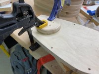
For the translam box and diffuser parts, I used a combination of laser cutting and conventional jigsaw and router work.
The diffusers are each 22 layers of 6 mm baltic birch. Because machining these on the router would have been so tedious, I had them laser cut by sendcutsend.com, so assembly was a matter of gluing up the stacks, sanding, and doing some post-machining of wiring and mounting holes.


For the woofer boxes, I had templates cut by sendcutsend.com, one out of aluminum for the dowel/indexing holes, the exterior, and the fully open layers, and one each for the layers having the woofer opening and the reinforcing bridges. It was then a matter of rough cutting with the jigsaw, drilling the dowel holes, and milling the shapes on the router...


...then gluing up the stack.

Giving myself 15 minutes max open time with Titebond polyurethane, I was able to do half a stack per session. The adhesive cures quickly and the squeeze-out (foam-out?) cleans of very easily.

After sanding to 220 grit, the finish is
For the translam box and diffuser parts, I used a combination of laser cutting and conventional jigsaw and router work.
The diffusers are each 22 layers of 6 mm baltic birch. Because machining these on the router would have been so tedious, I had them laser cut by sendcutsend.com, so assembly was a matter of gluing up the stacks, sanding, and doing some post-machining of wiring and mounting holes.
For the woofer boxes, I had templates cut by sendcutsend.com, one out of aluminum for the dowel/indexing holes, the exterior, and the fully open layers, and one each for the layers having the woofer opening and the reinforcing bridges. It was then a matter of rough cutting with the jigsaw, drilling the dowel holes, and milling the shapes on the router...
...then gluing up the stack.
Giving myself 15 minutes max open time with Titebond polyurethane, I was able to do half a stack per session. The adhesive cures quickly and the squeeze-out (foam-out?) cleans of very easily.
After sanding to 220 grit, the finish is
- One coat SealCoat dewaxed shellac, diluted 1:1 with denatured alcohol
- Three coats Aquaseal grain filler
- Timbermate filler in any little voids or tearouts that remained (not much!)
- Three coats General Finishes polyurethane, sanding with 320 grit between coats
- Sanding with 320 grit or a 3M maroon buffing pad to remove any flaws
- Buffing with a 3M gray buffing pad (00 steel wool equivalent)
- Final buffing with a 3M white buffing pad (0000 equivalent?)
Last edited:
With all respect ot you and Mr. Linkwitz, perhaps eliminate the uppermost internal stud? It is causing huge restriction of airflow. The mid-tweeter has minimal airflow, so not an issue really.

Last edited:
A few highlights covering specific details...
Installing threaded inserts for the woofer mount, and for the diffuser mount. The inserts for the woofers are M4 brass inserts, made for insertion into 3D printed parts. The inserts for the diffuser mounts are #6 which match standard wide-head screws used for drawer pulls. Later, the mounting holes in the top were enlarged to allow for fine adjustment of the diffuser position. The holes for the wiring were widened later as well.


The mounting block for the inset terminals...


If doing it again, I might pre-wire and install these, making sure they can be removed if necessary. On this build, they were installed after the box was closed up.
Finally, the fullrange mounts. These involved bending and threading brass rod for the two bottom pieces, and drilling the little "ears" on the diffusers to receive them. For the top, I took advantage of a mounting hole on the fullrange driver that's not on the Seas drawing. It lines right up with the top ear, and is the right size for an M3 thread. At the top 10 mm threaded insert plus a thin washer puts the driver at the correct distance from the diffuser.
.jpeg")
Later, I blackened the brass with Jax Pewter Black. With everything aligned, a drop of cyanoacrylate in each hole keeps the brass rods in place.
Installing threaded inserts for the woofer mount, and for the diffuser mount. The inserts for the woofers are M4 brass inserts, made for insertion into 3D printed parts. The inserts for the diffuser mounts are #6 which match standard wide-head screws used for drawer pulls. Later, the mounting holes in the top were enlarged to allow for fine adjustment of the diffuser position. The holes for the wiring were widened later as well.
The mounting block for the inset terminals...
If doing it again, I might pre-wire and install these, making sure they can be removed if necessary. On this build, they were installed after the box was closed up.
Finally, the fullrange mounts. These involved bending and threading brass rod for the two bottom pieces, and drilling the little "ears" on the diffusers to receive them. For the top, I took advantage of a mounting hole on the fullrange driver that's not on the Seas drawing. It lines right up with the top ear, and is the right size for an M3 thread. At the top 10 mm threaded insert plus a thin washer puts the driver at the correct distance from the diffuser.
Later, I blackened the brass with Jax Pewter Black. With everything aligned, a drop of cyanoacrylate in each hole keeps the brass rods in place.
Attachments
I perseverated about this, with exactly that concern. The actual gap at the bottom is 0.8", including the actual dimension of the magnet which is smaller than what's in the rending, and a bit of widening of the opening that's also not shown in this rendering.With all respect ot you and Mr. Linkwitz, perhaps eliminate the uppermost internal stud? It is causing huge restriction of airflow. The mid-tweeter has minimal airflow, so not an issue really.
View attachment 1036949
Maybe that's considered enough. In any event, ultimately decided to trust Mr. Linkwitz rather than thinning the walls or increasing the radius at the front. Comparing with the dimensions of the connector he used, specifically where it begins to taper, I determined that the opening is a little bit larger than in his original.
Wiring and final assembly
Wires were soldered to the terminals, then threaded through the mounting holes. I used enough silicone to provide a seal, but (I trust) not so much that these can't be removed if the need ever arises. Threading a socket wrench socket over the wires enabled me to tighten the nuts. Then the bottom was lined with 1/4" wool felt.


The fullrange drivers were wired separately so they can be removed if necessary. Wires are sealed with silicone where they pass through the diffuser mount.


Through all of the test fitting, I got pretty good at inserting the screws from the inside of the cabinet.
The prescribed quantity of Acousta-Stuff...

...and finally, both drivers mounted (photo taken before final trimming of the gasket and tightening of the mounting screws).

Wires were soldered to the terminals, then threaded through the mounting holes. I used enough silicone to provide a seal, but (I trust) not so much that these can't be removed if the need ever arises. Threading a socket wrench socket over the wires enabled me to tighten the nuts. Then the bottom was lined with 1/4" wool felt.
The fullrange drivers were wired separately so they can be removed if necessary. Wires are sealed with silicone where they pass through the diffuser mount.
Through all of the test fitting, I got pretty good at inserting the screws from the inside of the cabinet.
The prescribed quantity of Acousta-Stuff...
...and finally, both drivers mounted (photo taken before final trimming of the gasket and tightening of the mounting screws).
First test
This is a terrible environment for a far field test: 7.5' ceiling and somewhat crowded space.

Using the "stock" LXMini configuration for the MiniDSP 2x4HD DSP, adjusted only for differences in spec sheet gains of the woofer and fullrange amps, here's the response on the tweeter axis, gated at 3.8 ms (so very limited at the low end):

More/better measurements await having the right weather to work outdoors.
This is a terrible environment for a far field test: 7.5' ceiling and somewhat crowded space.
Using the "stock" LXMini configuration for the MiniDSP 2x4HD DSP, adjusted only for differences in spec sheet gains of the woofer and fullrange amps, here's the response on the tweeter axis, gated at 3.8 ms (so very limited at the low end):
More/better measurements await having the right weather to work outdoors.
- Home
- Loudspeakers
- Multi-Way
- LXMini variant build thread