Hi guys,
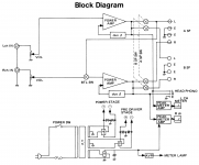
I am building the Luxman M-02 power amp from 1980's, featuring their unique "Duo-Beta" circuitry.
Here's what I found about "Duo-beta" with some adaptation:
***Brief
Duo Beta means there are TWO separate feedbacks with different gains.
Beta 1 works with the full frequency range and with low feedback-less than 37 dB.
Beta 2 handles the subsonic range (0-5Hz ) ONLY and with high feedback increasing to 0 at DC.
Therefore the damping factor is very high at low frequencies and with no phase angle change.
***Why Duo-Beta?
Generally a large amount of NFB (negative feedback) is introduced to enhance amplified characteristics. This method is highly effective when applied to stable wave-forms, such as sine waves, with static characteristics.
On the other hand, NFB can cause damaging effects to musical signals with dynamic characteristics. This occurs because input signals are constantly changing, never retaining the same shape when the reversed phase is returned from the output stage.*
With this in mind, only amplifiers that feature unbiased characteristics, without the need to rely on NFB, can be considered truly superb.
As such, Luxman places utmost priority on developing amplifiers that incorporate a superior open loop characteristic before NFB is applied.
When less NFB is applied, operation of the amplifier becomes less stable. Therefore, Luxman extract sound from the inaudible range by applying a DC servo to bring operational stability to reality. And to bring tight, well-tailored waveforms to the listening environment."
The result: smooth, clean reproduction of mid-to-high frequencies and tight, articulate bass response.
Spec of M-02:
Power Output :
From 20 Hz to 20 kHz:* 140 W per Channel at 8*Ω
At 1 kHz :* 140 W per Channel at 4 Ohms
BTL Power :* 300 W at 8 Ohms
Dynamic Power (1 kHz, IHF Signal):*
190 Watts at 8*Ω
290 Watts at 4*Ω
410 Watts at 2*Ω
Total Harmonic Distortion:* less than 0,025%
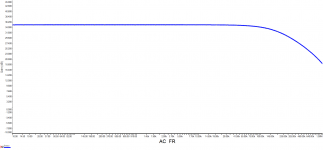
Frequency Response: 10 Hz to 100 kHz (-0,5 dB)
Signal-to-Noise Ratio:* greater than 120 dB
Input Sensitivity/Impedance:* 1,2 V/ 45 k*Ω
-----------------------------------------------------------------------
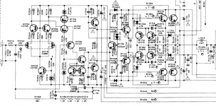
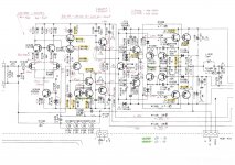
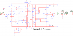
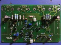
Based on the original schematic, I extract the main power amp part, using some modern easy-to-find parts.
Any suggestions are welcomed, also any discussion about the Duo-beta by Luxman.🙂
I am building the Luxman M-02 power amp from 1980's, featuring their unique "Duo-Beta" circuitry.
Here's what I found about "Duo-beta" with some adaptation:
***Brief
Duo Beta means there are TWO separate feedbacks with different gains.
Beta 1 works with the full frequency range and with low feedback-less than 37 dB.
Beta 2 handles the subsonic range (0-5Hz ) ONLY and with high feedback increasing to 0 at DC.
Therefore the damping factor is very high at low frequencies and with no phase angle change.
***Why Duo-Beta?
Generally a large amount of NFB (negative feedback) is introduced to enhance amplified characteristics. This method is highly effective when applied to stable wave-forms, such as sine waves, with static characteristics.
On the other hand, NFB can cause damaging effects to musical signals with dynamic characteristics. This occurs because input signals are constantly changing, never retaining the same shape when the reversed phase is returned from the output stage.*
With this in mind, only amplifiers that feature unbiased characteristics, without the need to rely on NFB, can be considered truly superb.
As such, Luxman places utmost priority on developing amplifiers that incorporate a superior open loop characteristic before NFB is applied.
When less NFB is applied, operation of the amplifier becomes less stable. Therefore, Luxman extract sound from the inaudible range by applying a DC servo to bring operational stability to reality. And to bring tight, well-tailored waveforms to the listening environment."
The result: smooth, clean reproduction of mid-to-high frequencies and tight, articulate bass response.
Spec of M-02:
Power Output :
From 20 Hz to 20 kHz:* 140 W per Channel at 8*Ω
At 1 kHz :* 140 W per Channel at 4 Ohms
BTL Power :* 300 W at 8 Ohms
Dynamic Power (1 kHz, IHF Signal):*
190 Watts at 8*Ω
290 Watts at 4*Ω
410 Watts at 2*Ω
Total Harmonic Distortion:* less than 0,025%
Frequency Response: 10 Hz to 100 kHz (-0,5 dB)
Signal-to-Noise Ratio:* greater than 120 dB
Input Sensitivity/Impedance:* 1,2 V/ 45 k*Ω
-----------------------------------------------------------------------
Based on the original schematic, I extract the main power amp part, using some modern easy-to-find parts.
Any suggestions are welcomed, also any discussion about the Duo-beta by Luxman.🙂
Attachments
Last edited:
There is a lot of marketing twaddle in all that and so I hope this doesn't all sound to negative 🙂
I would doubt that Luxmans design engineers don't understand how feedback works, but having read that I'm not so sure.
Where is the 'DC servo' ?
While its a fairly complex and refined design, it all seems to follow a standard topology with the exception of the slightly odd feedback arrangement.
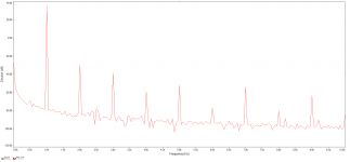
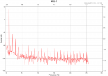
The 45k input impedance looks a bit suspect too. Your final FFT simulation looks a little grim tbh, even considering the very high output level. The 2nd harmonic looks to be only at around -30db on that graph.
It is what it is, a design of the 80's.
I would doubt that Luxmans design engineers don't understand how feedback works, but having read that I'm not so sure.
Where is the 'DC servo' ?
While its a fairly complex and refined design, it all seems to follow a standard topology with the exception of the slightly odd feedback arrangement.
The 45k input impedance looks a bit suspect too. Your final FFT simulation looks a little grim tbh, even considering the very high output level. The 2nd harmonic looks to be only at around -30db on that graph.
It is what it is, a design of the 80's.
Thank you for your comments.
My attempt is to experience the "80's Japan-made" Amp😀
But, any suggestions about circuit improvements? Appreciate that.
Best,
Eric
My attempt is to experience the "80's Japan-made" Amp😀
But, any suggestions about circuit improvements? Appreciate that.
Best,
Eric
There is a lot of marketing twaddle in all that and so I hope this doesn't all sound to negative 🙂
I would doubt that Luxmans design engineers don't understand how feedback works, but having read that I'm not so sure.
Where is the 'DC servo' ?
While its a fairly complex and refined design, it all seems to follow a standard topology with the exception of the slightly odd feedback arrangement.
The 45k input impedance looks a bit suspect too. Your final FFT simulation looks a little grim tbh, even considering the very high output level. The 2nd harmonic looks to be only at around -30db on that graph.
It is what it is, a design of the 80's.
Its hard to say really, at least not without testing and verifying results.
If this is for domestic use (for you) then I would probably omit all the complex overcurrent protection. If you want to stick with bjt outputs then you need to look at what is available. The originals were pretty poor in terms of Ft (frequency where the current gain falls to 1) but were pretty good in terms of current gain at the frequencies of interest (audio band).
You could look at substituting the bjts with vertical FET's as one possible direction for modification. Their ease of drive could give benefits. Even more intriguing might be to see how lateral FET's would perform.
On the other hand, if you want to experience it as it was designed then you have to stay true to the original concept as closely as possible.

- Status
- Not open for further replies.
- Home
- Amplifiers
- Solid State
- Luxman M-02 Build and Duo-beta circuit