Hi, I have a problem with
my Luxman I-80v
The main filter caps were
replaced due to them previously bursting and with the new replacements it played music for a while then shortly after the 125v 5a fuse popped. Do you have any idea of what this might be?
Any Help Would Be Much Appreciated
Thanks
Thanks
my Luxman I-80v
The main filter caps were
replaced due to them previously bursting and with the new replacements it played music for a while then shortly after the 125v 5a fuse popped. Do you have any idea of what this might be?
Any Help Would Be Much Appreciated
Thanks
Thanks

replaced due to them previously bursting and with the new replacements it played music for a while then shortly after the 125v 5a fuse popped. Do you have any idea of what this might be?
You show as being in the UK and so the first question is what is the 125 v fuse referring to. Filter caps (you mean the big reservoir caps?) burst previously. Could this be a 120v unit running on 230v UK mains? Are the replacements fitted the correct way around? Are the replacements of known good quality (not eBay where many fakes exists)?
Use a DBT (dim bulb tester) before powering it up again. See what the state of play is and whether the rails come up or whether something has failed short circuit.Any Help Would Be Much Appreciated
Hi, When I mention 125V 5A I'm referring to a Glass protection fuse. The system has a foreign plug so is being powered on a adapter
This is how I believe this unit was powered previously. I have attached an image of the plug (FYI: It is 15A 150v)

This worked for over 45 years but was stored in the loft for a while. After retrieving it from my loft straight after powering it on it made an aggressive humming sound so I turned it off but on the second power on the main power filter caps exploded releasing awful smoke. Since then I replaced the three 0.3A 250v fuses and it powered on still with the faulty caps so I ordered new caps and installed them a few days back. Music played from the system as mentioned previously but after a bit the 5A 125V fuse burst into a green spark and the new caps seemed to be no longer working Especially as I replaced the 5A 125v with the only fuse I had of 5A 250v and installed the same caps again but sounds of shorting / zapping was heard when power button pressed so i let it rest. To note, the time when the new caps were installed and the fuse blew only one capacitor (50v 10000uf was hot and seemed like it was expanding slightly but was still intact despite it starting to smell)
Getting this working would mean the world
Any help would be much appreciated
Thanks
Getting this working would mean the world
Any help would be much appreciated
Thanks
OK 🙂
Well the first thing to do is give it a good visual inspection internally. You can check for basic failures (short circuits) of the bridge rectifier and output transistors.
If nothing obvious is then you power it up but you MUST then use a DBT to limit current in the event of any overloads. Then it is a case of some basic voltage checks. If the bulb is brightly lit you have an overload (short) somewhere which then needs locating.
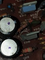
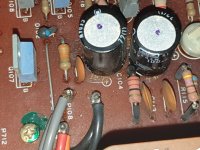
I see you mention one of the caps was hot. Only two things will do that, either it is in back to front and so reverse biased or there is a problem with the bridge rectifier.
Well the first thing to do is give it a good visual inspection internally. You can check for basic failures (short circuits) of the bridge rectifier and output transistors.
If nothing obvious is then you power it up but you MUST then use a DBT to limit current in the event of any overloads. Then it is a case of some basic voltage checks. If the bulb is brightly lit you have an overload (short) somewhere which then needs locating.
I see you mention one of the caps was hot. Only two things will do that, either it is in back to front and so reverse biased or there is a problem with the bridge rectifier.
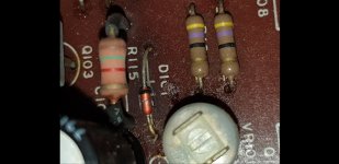
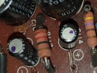
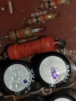
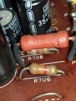
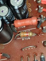
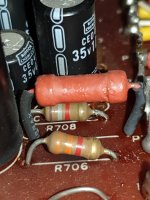
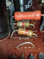
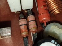
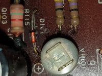
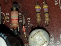
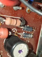
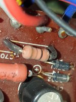
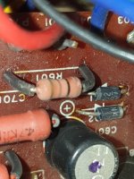
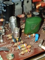
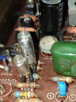
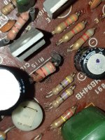
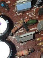
Hi, I have been testing resistors, diodes, output transistors ,capacitors, for the past 2 days using my multi meter. The bridge diodes mostly measuring and dropping between 2.8v and 0.5volts. But majority of the power supply capacitors are either becoming loose or way under their rated capacitance due to age. (All this testing has been carried out in circuit). I also see some other metal coated red resistors rated for 4.7kohms but only reading about two. Apart from that majority of the components such as resistors etc seem to have handled alot of stress/ heat as some seem very dry/ crusty with what look likes black residue behind them supposedly from the heat. From here Im all out of ideas but I still have some elevated insulated resistors to test that arent surface mounted and some seem very dry / burnt but I will keep you updated on the readings. However I do find this very strange as it was indeed playing music from its auxiliaries but the fuse blew so clearly some problems must persist. I was also wondering whether recapping the several smaller power supply electrolytic capacitors that are coming loose and reading over half under their rated capacitance may help with this situation.
Waiting For your reply.
Many Thanks
Waiting For your reply.
Many Thanks
Testing in circuit is often problematic although it will show shorts and also essentially allow measurement of low value resistors.
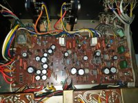
A good picture of the board might help us understand what state this is all in but I suspect its probably not that bad...
The only way to tackle this is to do live measurements with it powered up (but using the DBT) and see where it is at.
I wouldn't advise replacing any more parts at this stage, you have to do measurements. Also think on what I said over the caps overheating. There are really only those two reasons why, so do check the orientation of them is correct. If they are PCB mounted then do not rely on board markings as they can occasionally be in error. Confirm by measurement (continuity check) that the caps go to the correct points and are not reverse biased.
On the amp there should be a lable that tells you the power rating of the unit!
If there was an overvoltage of twice the amount i would not be surprised if some transistors havve been damaged as well.
If the power rating was correct then you are lucky as only the capacitors need to be replaced. Measuring a defective amp must be done with a variable power source (variac) and the feedbackloop disabled. An oscillosope is very handy in this case.
Please See Attached
Attachments
-
 Screenshot_20230304-182322_Gallery.jpg200.6 KB · Views: 45
 -
 20230304_182250.jpg407.7 KB · Views: 51
 -
 20230304_182230.jpg360.5 KB · Views: 48
 -
 20230304_182219.jpg437.3 KB · Views: 59
 -
 20230304_182221.jpg493 KB · Views: 53
 -
 20230304_182216.jpg426.7 KB · Views: 52
 -
 20230304_182213.jpg427.4 KB · Views: 54
 -
 20230304_182204.jpg377 KB · Views: 54
 -
 20230304_182150.jpg450.7 KB · Views: 59
 -
 20230304_182147.jpg462.4 KB · Views: 55
 -
 20230304_182128.jpg472.2 KB · Views: 48
 -
 20230304_182131.jpg456.9 KB · Views: 42
 -
 20230304_182125.jpg462.3 KB · Views: 61
 -
 20230304_182107.jpg478.6 KB · Views: 57
 -
 20230304_182115.jpg461.9 KB · Views: 51
 -
 20230304_182058.jpg512.7 KB · Views: 56
 -
 20230304_181900.jpg411.3 KB · Views: 55
 -
 20230304_181916.jpg641.7 KB · Views: 54
 -
 20230304_181857.jpg379.4 KB · Views: 56
 -
 20230304_181844.jpg495.6 KB · Views: 50
Hopefully not alot of damage has been done however I still find this very odd especially as this was how the amp was powered for the odd part of 40 years with no Problems.On the amp there should be a lable that tells you the power rating of the unit!
If there was an overvoltage of twice the amount i would not be surprised if some transistors havve been damaged as well.
If the power rating was correct then you are lucky as only the capacitors need to be replaced. Measuring a defective amp must be done with a variable power source (variac) and the feedbackloop disabled. An oscillosope is very handy in this case.
Maybe it was used with a dedicated transformer at the time.
Now it is the task to check the danage.
Now it is the task to check the danage.
- Home
- Amplifiers
- Solid State
- Luxman Diagnoses Help