Eli Duttman,
Thanks for the schematics.
BTW: I have never built any tube amp, but a colleague of mine borowed me his modified Dyna and Lafayette amp.
I liked the Dyna, but it did not have nice highs.
trif.
Note: I have auditioned those amps in my listening room/studio. That room is acoutically treated (with many acoutic panels and long soffits) and the freq response in it is extremely flat and the decay times are well under control.
Hi Trifidmaster
The 3rd edition of Valve amplifiers, by Morgan Jones, shows a schematic with the tubes and circuit you want: a ECC88 as driver/phase splitter (concertina) and 2 EL84's at the output.
Erik
The 3rd edition of Valve amplifiers, by Morgan Jones, shows a schematic with the tubes and circuit you want: a ECC88 as driver/phase splitter (concertina) and 2 EL84's at the output.
Erik
trifidmaster said:Eli Duttman,
I liked the Dyna, but it did not have nice highs.
It does not depend on the schematic which is classical in this particular case. With different output transformers you'll get very different results.
However, I would decrease impedance of the feedback loop 10 times splitting cathode resistor by 1.2K bypassed by a capacitor and 100 Ohm in series, 27K resistor in the feedback would be reduced to 2.4K. Correspondingly, the capacitance in parallel with this resistor will be increased until the amp get stable on highs. Or, you may leave the cathode resistor as is, connect to the cathode one 100 Ohm resistor with 1000 microFarad capacitor in series, negative leg of the cap is grounded, and feedback will go to the point of interconnection of the 100 Ohm resistor and the capacitor.
It will decrease a local feedback in the 1'st stage increasing gain; the overall feedback will bne deeper, and non-lineariries in the feedback loop will be reduced many times.
Wavebourn said:
It does not depend on the schematic which is classical in this particular case. With different output transformers you'll get very different results.
However, I would decrease impedance of the feedback loop 10 times splitting cathode resistor by 1.2K bypassed by a capacitor and 100 Ohm in series, 27K resistor in the feedback would be reduced to 2.4K. Correspondingly, the capacitance in parallel with this resistor will be increased until the amp get stable on highs. Or, you may leave the cathode resistor as is, connect to the cathode one 100 Ohm resistor with 1000 microFarad capacitor in series, negative leg of the cap is grounded, and feedback will go to the point of interconnection of the 100 Ohm resistor and the capacitor.
It will decrease a local feedback in the 1'st stage increasing gain; the overall feedback will bne deeper, and non-lineariries in the feedback loop will be reduced many times.
Oops... Sorry for the mistake, feedback will go to the cathode, of course!
One more way to reduce distortions is to use the amp in inverting mode when both input and feedback is connected to the same grid, but it is good when you are driving the amp from low and known impedance. Cathode resistor in such case should be bypased by a cap, and output transformer taps must be inverted.
Eli Duttman said:The Dyna ST35 schematic here.
Just a note: I've seen that schematic floating around the web. It was redrawn in error, leaving out the 60uF section of the power supply cap, which should be connected from the HV rectifier diodes to ground. This page has a scan of the original, although details are hard to read.
Dynaco page
Dear gens!
Thank you very much for your comments!!!
🙂
..this is getting exiting...
I have the 3rd edition of Valve amplifiers, by Morgan Jones book.
He uses the ECC88, indeed.
Is the ECC88 replacable with the 6922?
I already have the Lundahl trafos, they look very cool - I hope they will sound warm, too.
I also have the EL84 tubes/sovtek, matched.
And the 6922s are with me too.
The power supply will be with chookes, and tube diode.
BTW: the enclosure is ready (no wood-cover/frame work yet).
I have used all the advices for my enclosure from Morgan Jones-building Valve Amps.
LOTS of work, but I think the end result looks nice.
trif.
Is the ECC88 replacable with the 6922?
Yes!
In this thread Kofi Annan reports his building of the Bevois Valley, lots of information and fun!
http://www.diyaudio.com/forums/showthread.php?s=&threadid=62597&perpage=20&pagenumber=1
Good luck
Erik
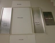
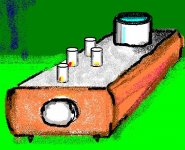
Here is the materail layout and the "dry" material assembly.
As you can see the left/right plates are made from U-profile.
The front/back/bottom/top plates are made from 3 mm thick brushed and anodized aluminum plates (the top plate is not on the photo).
On the left side you can see a "smaller" plate called Power trafo plate.
The purpose of this plate is visible from the assembly picture.
trif.
Attachments
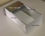
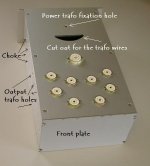
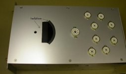
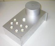
And finally the assembled enclosure. No inside electrical work is yet done. The power trafo is big, and will be on the top of the enclosure.
Note: the choke(s) (1 choke/channel) and the output trafos are inside the enclosure - I have indicated the fixation holes for these trafos.
On the front panel the hole for the potmeter is still missing.
trif.😉
Note: the choke(s) (1 choke/channel) and the output trafos are inside the enclosure - I have indicated the fixation holes for these trafos.
On the front panel the hole for the potmeter is still missing.
trif.😉
Attachments

Karma,
Thanks for the good words.
I wanted to have an ellongated design, so the top plate is 400mmx220mm.
I have made sure that the center of the tubes are 50mm from each other. As I wrote, I will use 1 choke/channel (the chokes are also nicely visible in the "inner" picture).
trif.
Thanks for the good words.
I wanted to have an ellongated design, so the top plate is 400mmx220mm.
I have made sure that the center of the tubes are 50mm from each other. As I wrote, I will use 1 choke/channel (the chokes are also nicely visible in the "inner" picture).
trif.
- Status
- Not open for further replies.
- Home
- Amplifiers
- Tubes / Valves
- Lundahl+EL84 PP+concertina+input stage